REVISION HISTORY
REV. |
DESCRIPTION OF MODIFICATION |
DATE |
1 |
First Issue for Comment |
5 Mar 2020 |
2 |
Revision according to EPD’s comments |
3 Jun 2020 |
3 |
Revision according to EPD’s comments |
10 Nov 2020 |
4 |
Revision according to EPD’s comments |
29 Jan 2021 |
5 |
Revision according to RSS’s and IEC’s comments |
18 Jan 2022 |
6 |
Revision according to EPD’s comments |
31 Mar 2022 |
7 |
Update of implementation schedule of Table 2.1 |
01 Mar 2024 |
8 |
Revision according to revised slope mitigation works design |
13 Feb 2026 |
9 |
Revision according to EPD’s comments |
13 Mar 2026 |
10 |
Revision according to EPD’s and PlanD’s comments |
29 April 2026 |
11 |
Revision according to PlanD’s comment |
12 June 2026 |
12 |
Revision according to EPD’s comment |
3 Jul 2026 |
CONTENTS
Page
1. Introduction ..................................................................................................................................................................... 5
1.1. Background ............................................................................................................................................................. 5
1.2. Contract Description ........................................................................................................................................... 6
1.3. Purpose of the Plan .............................................................................................................................................. 6
1.4. Update of the plan ................................................................................................................................................ 7
2. Proposed Landscape and Visual Mitigation Measures ................................................................................... 8
3. Aesthetic Landscape and Architectural Treatment for Above Ground Structures ........................... 15
3.1. Minimization of Construction Area and Area for Temporary above Ground Structures (MM1) .................................................................................................................................................................................... 15
3.2. Minimization of Above Ground Structures (MM2) ............................................................................... 15
3.3. Aesthetic Landscape and Architectural Treatment for Above Ground Structures (MM3) .. 16
3.3.1. Green roof ................................................................................................................................................... 16
3.3.2. Roadside planting .................................................................................................................................... 16
3.3.3. Vertical greening ...................................................................................................................................... 17
3.3.4. Screening planting along the site ...................................................................................................... 17
3.3.5. Landscape areas ....................................................................................................................................... 17
3.3.6. Aesthetic treatment of all structures ............................................................................................... 17
3.3.7. Fairface finishing ..................................................................................................................................... 18
3.3.8. Prefabricated fairface concrete façade cladding......................................................................... 18
3.3.9. Paving materials ....................................................................................................................................... 19
3.3.10. Permeable perimeter fence ................................................................................................................. 19
3.3.11. Architectural feature fins ..................................................................................................................... 19
3.4. Slope Mitigation Works (MM6) .................................................................................................................... 19
3.5. Lighting Arrangement (MM8) ....................................................................................................................... 21
3.5.1. General ......................................................................................................................................................... 21
3.5.2. Garden Lights in Operation Phase .................................................................................................... 22
4. Tree Felling and Preservation Proposal (MM4) .............................................................................................. 23
5. Construction Mitigation Measures ....................................................................................................................... 24
5.1. Blending in with the Existing Landscape and Visual ........................................................................... 24
5.2. Providing soft landscaping ............................................................................................................................. 25
5.3. Conserving/Recovering Existing Greenery ............................................................................................. 25
5.4. Implementing Good Site Practices/ Other Recommended Mitigation Measures .................... 25
5.5. Conducting Regular Site Audit ...................................................................................................................... 25
6. Conclusion ....................................................................................................................................................................... 25
LIST OF APPENDICES
Appendix A
Layout Plan of Works Area under Contract No. 13/WSD/17 Appendix B
Tree Survey Result
Appendix C
Implementation of L&V Mitigation Measure (Operation Stage) Appendix D
DPTKO Building Layout Plan
Appendix E
Soft Landscape Design
Appendix F
Hard Landscape Design
Appendix G
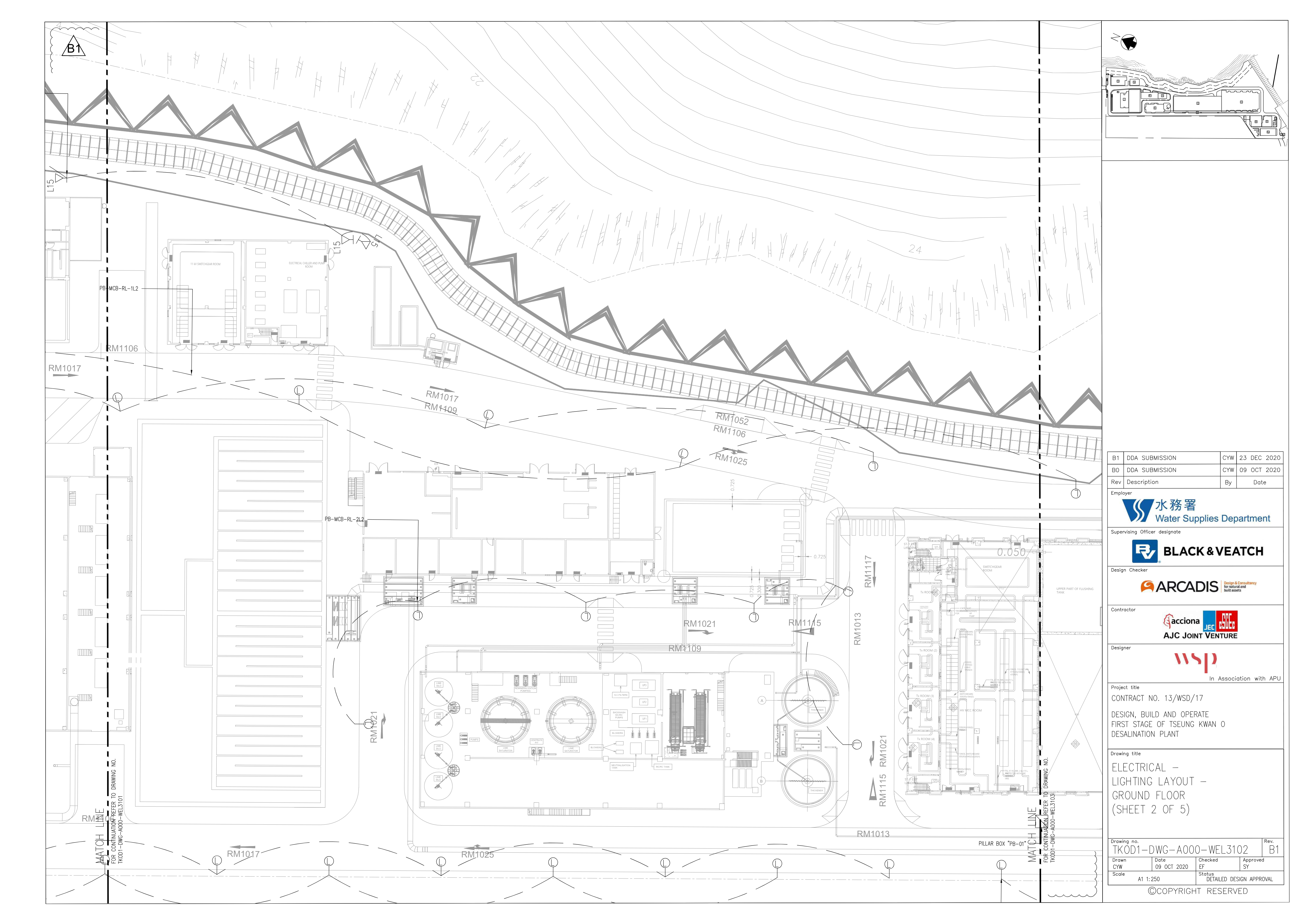
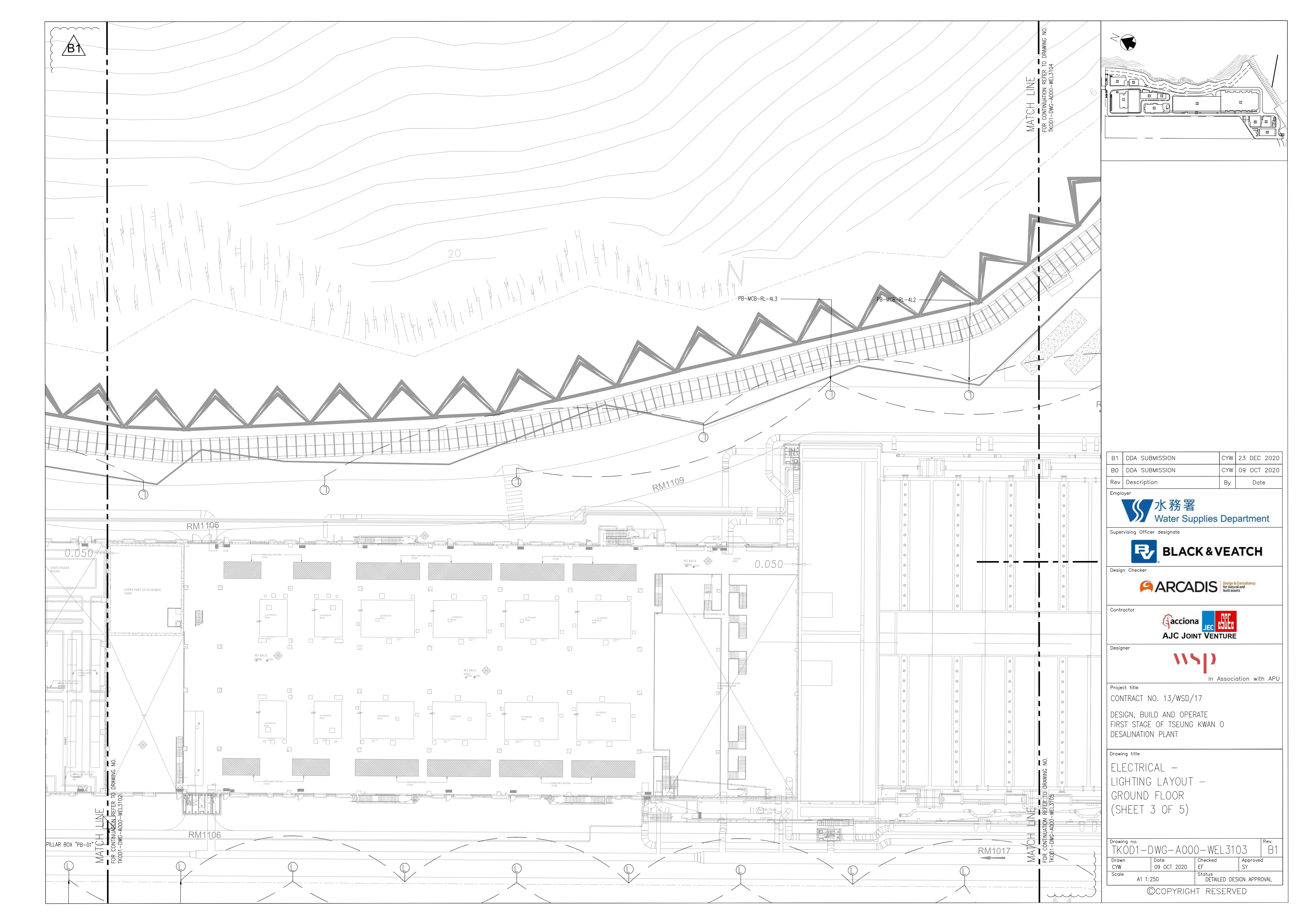
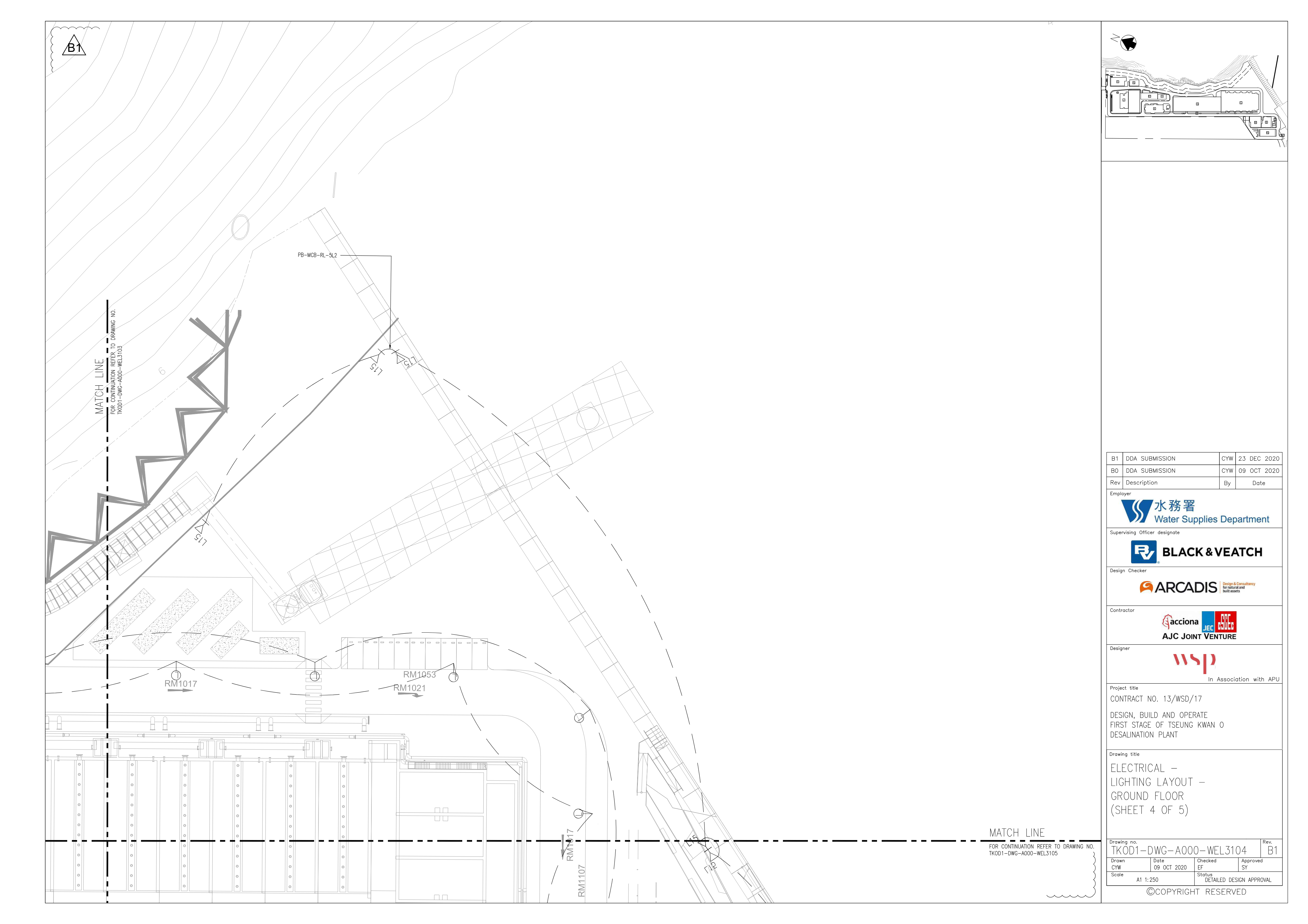
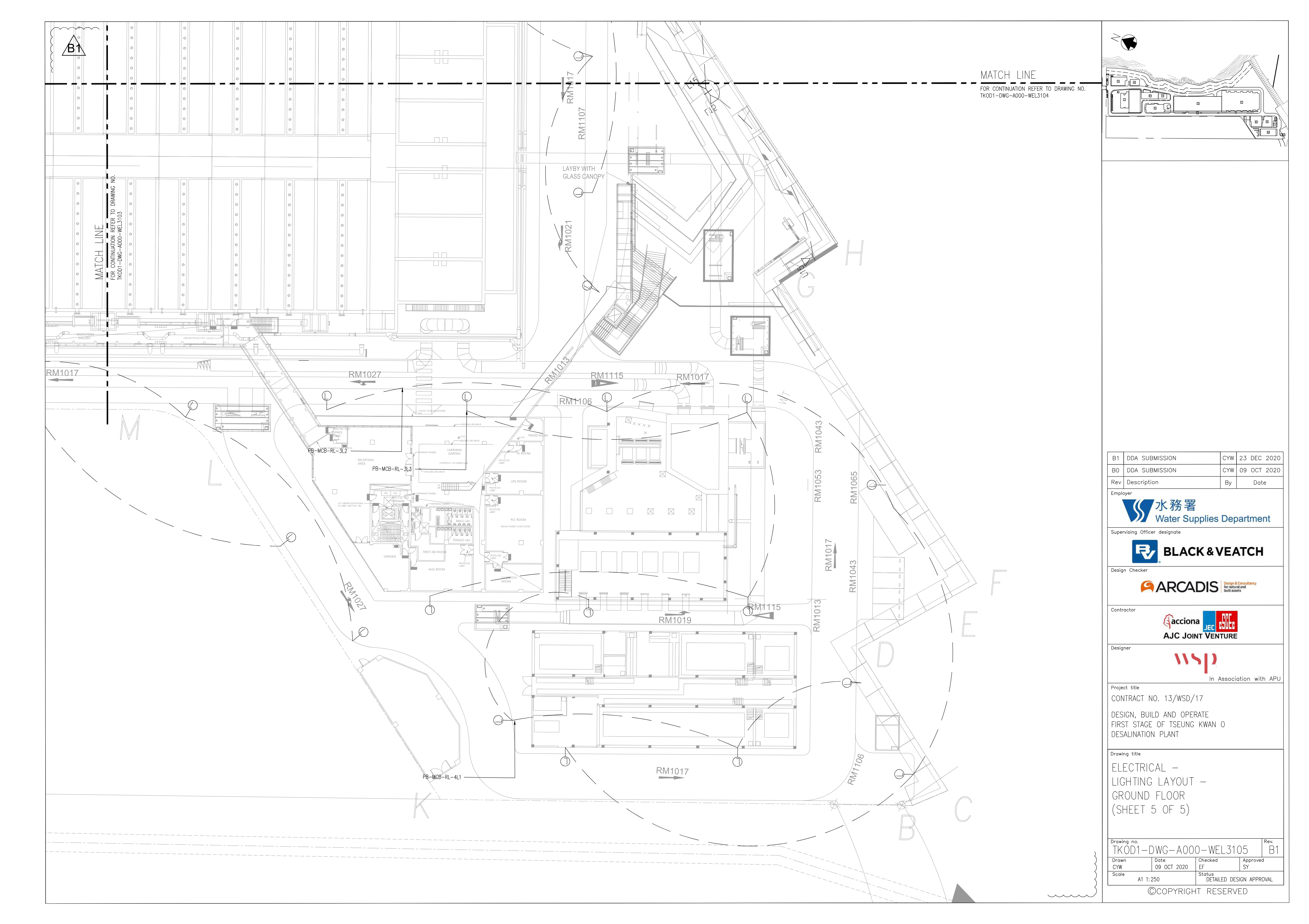
Lighting Plan
Appendix H
Detailed Design for Slope Mitigation Works
1. INTRODUCTION
1.1. BACKGROUND
Pursuant to the Environmental Impact Assessment Ordinance (EIAO), the Director of Environmental Protection granted the Environmental Permit (No. EP-503/2015) and Variation of Environmental Permit (No. EP-503/2015/B) to Water Supplies Department (WSD); and granted the Further Environmental Permit (No. FEP-01/503/2015/B) to AJCJV for the Contract.
The Acciona Agua, S.A. Trading, Jardine Engineering Corporation, Limited and China State Construction Engineering (Hong Kong) Limited As AJC Joint Venture (AJCJV) is contracted by WSD to carry out the Design, Build and Operate First Stage of Tseung Kwan O Desalination Plant (DPTKO) under Contract No. 13/WSD/17 (“the Contract”). The Further Environmental Permit (No. FEP- 01/503/2015/B) to AJCJV to construct the designation contract.
Acuity Sustainability Consulting Limited (ASCL) is commissioned by AJCJV to undertake the Environmental Team (ET) services as required and/or implied, both explicitly and implicitly, in the Environmental Permit (EP), Environmental Impact Assessment Report (EIA Report) (Register No.
AEIAR-192/2015) and Environmental Monitoring and Audit Manual (EM&A Manual) for the Contract;
and to carry out the Environmental Monitoring and Audit (EM&A) programme in fulfillment of the EIA Report’s EM&A requirements and Contract No. 13/WSD/17 Specification requirements.
Before WSD taking over the area for DPTKO development, the construction and demolition (C&D) materials being stockpiled and grown vegetation had been removed for construction projects. Prior to being handed over the area for DPTKO development, the area for the proposed desalination plant had been cleared of the stockpiled C&D materials and grown vegetation. It was then handed over to WSD when the finished ground level reached +5.2mPD.
In 2017, design variations of Contract were proposed, the design variations in relation to landscape and visual impacts are mainly the changes in Contract layouts, which includes; the relocation of building blocks with increase in building height within the original earmarked site defined in the EIA report; the reduction of the site area for desalination plant and; the reduction of slope mitigation works inside the Clear Water Bay Country Park (CWBCP). In 2025, design variations in relation to the reduction of slope mitigation works were further proposed to alleviate the high construction risk after frequent landslides.
The change in magnitude of landscape and visual impacts of the design variations from the EIA report have been thoroughly assessed and discussed in the Environmental Review Report (ERR) prepared by Black & Veatch (now known as Binnies HK Ltd.) on 03 November 2017. The ERR has concluded that the revised Contract layout will not change the overall landscape and visual impact levels presented in the EIA Report with mitigation measures in place. No additional mitigation measures are considered required for the proposed Contract variations. The environmental outcome from landscape and visual perspectives anticipated in the EIA Report will remain valid and applicable to the latest design.
1.2. CONTRACT DESCRIPTION
The Contract includes the following key components/works:-
Stage 1 Desalination Plant works (undertaken by Contract No. 13/WSD/17) •
construction of the seawater treatment components for the First Stage of the proposed desalination plant with a water production capacity at 135,000 cubic metres (m3) per day and with provision for future expansion to the ultimate water production capacity at 270,000 m3 per day when necessary, and associated facilities;
• formation of an eight-hectare site in TKO Area 137 for the construction of the proposed desalination plant and associated facilities with the ultimate water production capacity at 270,000 m3 per day;
• construction of the intake and outfall facilities of the proposed desalination plant to cater for the ultimate water production capacity of the proposed desalination plant at 270,000 m3 per day.
• natural slope mitigation works within the Clear Water Bay Country Park, which overlooks the northeast boundary of the desalination plant at TKO Area 137; and •
associated works including engineering, environmental mitigation works and landscaping works.
Stage 2 Desalination Plant works (to be undertaken in other works contract(s)) •
(under planning stage);
Freshwater Main Alignment (undertaken by Contract No. 13/WSD/16) A dedicated trunk feed system including about 9 km long water mains for the transfer of freshwater output from the desalination plant to the existing Tseung Kwan O Fresh Water Primary Service Reservoir in Po Lam.
1.3. PURPOSE OF THE PLAN
According to Condition 2.11 of the FEP and EP-503/2015/B, a landscape and visual mitigation proposal shall be submitted to the Director of Environmental Protection for approval no later than 1 month before the commencement of construction of the desalination plant of the Contract. The proposal, with drawings in the scale of 1:1000 or other appropriate scales as agreed by the Director, shall show the landscape and visual mitigation measures of the Contract, and shall include at least the following information:
(1) aesthetic landscape and architectural treatment for above ground structures;
(2) tree felling and preservation proposal showing quantity, plant species, location(s) and size of trees to be retained/transplanted/felled/compensated, and location(s) of transplanted trees;
(3) Landscape Plan showing location(s) of greening works including green roofs, roadside planting, vertical greening, screen planting, amenity planting, edge treatment along boundary and any other landscape enhancement to mitigate landscape impact of the Contract.
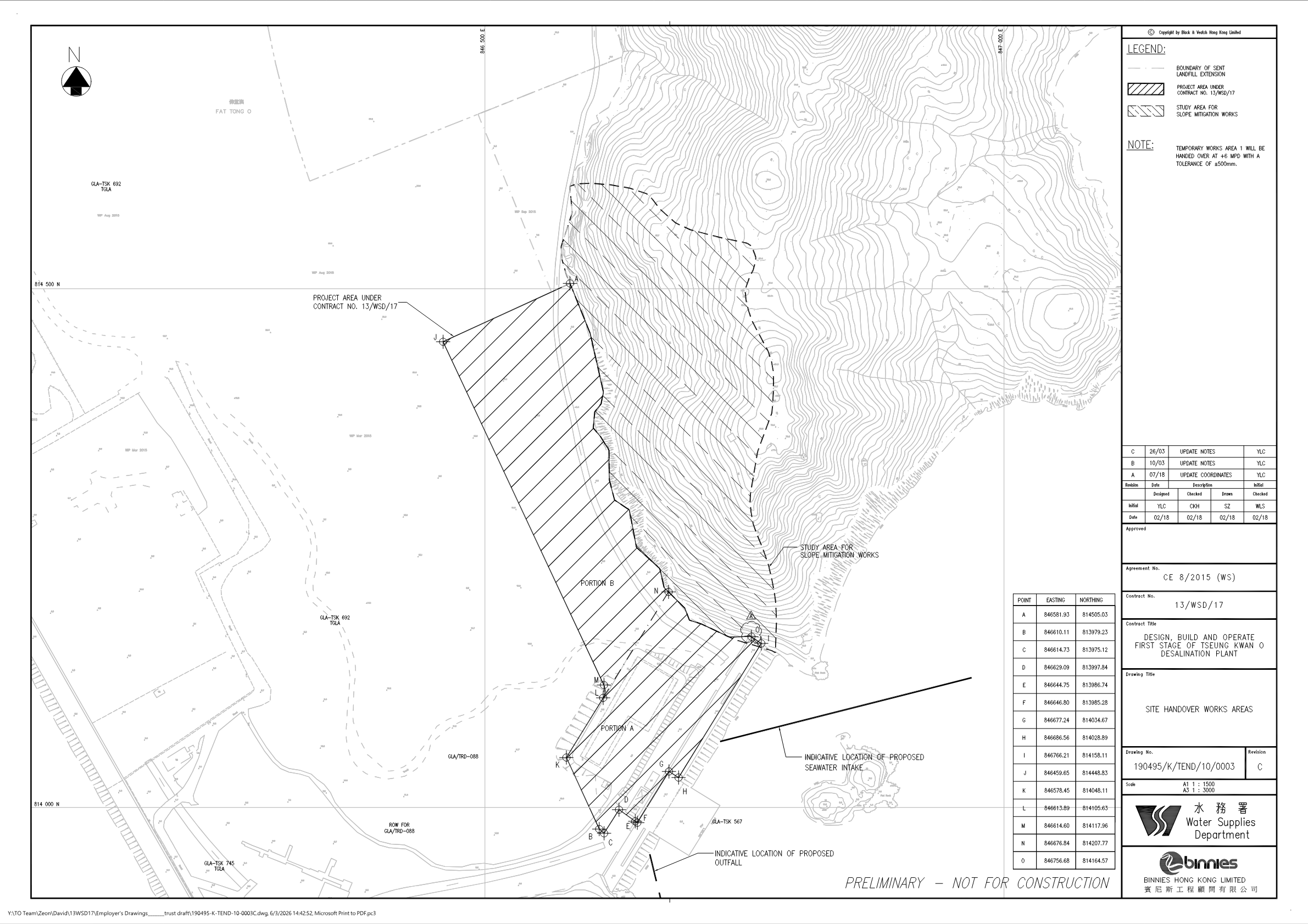
The scope of this LVMP covers the landscape and visual mitigation measures under Contract No.
13/WSD/17. The site layout plan for Contract No. 13/WSD/17 is shown in Appendix A. Before submission to the Director, the Landscape and Visual Mitigation Proposal shall be certified by the Environmental Team (ET) Leader and verified by the Independent Environmental Checker (IEC) as conforming to the requirements and recommendations contained in the EIA Report (Register No.
AEIAR-192/2015), EP/FEP and ERR. All measures recommended in the approved Proposal shall be fully and properly implemented and maintained for the Contract.
1.4. UPDATE OF THE PLAN
In accordance with EP Condition 2.7, the Updated Vegetation Survey for Slope Mitigation Works (Issue 212‑2) was submitted on 24 July 2017 and subsequently approved by the EPD on 31 August 2017 (hereinafter referred to as the “2017 Vegetation Survey”). The 2017 Vegetation Survey Report documented the survey findings, assessed the potential impacts, if any, arising from the proposed slope mitigation works, and recommended appropriate protection and mitigation measures for plant species of conservation importance identified during the 2016 survey. A revised report was later prepared to update the 2017 Vegetation Survey by incorporating the findings of subsequent vegetation surveys conducted in 2020, 2021, and 2023 (hereinafter referred to as the “2026 Vegetation Survey”). The 2026 Vegetation Survey was submitted to EPD on 12 February 2026 and subsequently approved on 9 March 2026.
In accordance with EP Condition 2.8, the Detailed Design Plan for Slope Mitigation Works (Issue 214‑2) was submitted on 2 March 2018 and subsequently approved by the EPD on 20 April 2018 (hereinafter referred to as the “2018 DDP”). The 2018 DDP detailed the proposed slope mitigation works, including the installation of a flexible barrier, rock slope stabilisation works, boulder removal, and boulder break‑off.
A series of extreme weather events subsequently occurred in Hong Kong, including a 1‑in‑500‑year black rainstorm and Typhoons Saola and Koinu in September and October 2023, as well as an amber rainstorm in May 2024. These events triggered multiple landslides within the slope area located in Clear Water Bay Country Park. Following a review of the severity and frequency of the landslides in the relevant slope area in consultation with the Civil Engineering and Development Department (CEDD), and taking into account the low usage frequency and low risk to life and property at the slope toe area, the extent and arrangement of the slope mitigation works within Clear Water Bay Country Park were re‑examined. A reduced extent and revised arrangement of slope mitigation works were subsequently proposed to the Geotechnical Engineering Office (GEO) / CEDD. GEO/CEDD provided no further comments on the design of the slope mitigation works in its memorandum dated 4 March 2025 (Ref.: ( ) in ME‑30‑2025‑12‑226‑1). In accordance with EP Condition 2.8, the Detailed Design Plan for Slope Mitigation Works was updated to reflect the revised slope mitigation works design.
The updated Detailed Design Plan was subsequently approved by EPD on 22 June 2026 (hereinafter referred to as the “2026 DDP”).
The 2018 DDP presented the initial tree survey results within the project area, and the slope mitigation works area, which were conducted by WSD in November 2015 and March 2016. CEDD carried out an extensive tree felling exercise in 2018 in accordance with their approved tree felling application (LandsD’s approval memorandum ref. (30) in LM 2 to DLO/SK 651/SGS/59 Pt.6 dated 23 October 2018), prior to site handover to WSD in December 2019. Upon handover of the site in December 2019, tree surveys were conducted within the desalination plant site and along the temporary access for boulder removal and stabilisation by break-off works in February and August 2020 to establish a new baseline record of the existing trees by WSD following site handover. After the February and August 2020 tree surveys, it was identified that certain trees had not been felled by CEDD in accordance with CEDD’s approved tree felling application. Consequently, CEDD conducted additional tree felling operations in accordance with their approved application to remove those trees originally proposed for felling. In the subsequent period, the site was affected by typhoons and adverse weather conditions. As a result, prior to the commencement of the slope mitigation works, another series of tree surveys was carried out by WSD in February, May, and June 2022, and February 2023 within the desalination plant site, the areas for rock slope stabilisation works, the area for the proposed flexible barrier, and along the temporary access for boulder removal and stabilisation by break-off works. The 2026 DDP presents updated information based on the tree surveys carried out in February and August 2020, February, May and June 2022, and February 2023.
In accordance with EP Condition 2.10, the Landscape and Visual Mitigation Proposal (Rev. 7) was submitted on 1 March 2024 and subsequently approved by EPD on 8 March 2024 (hereinafter referred to as the “2024 LVMP”). Section 3.4 of the approved LVMP presents details of the slope mitigation works and the corresponding landscape and visual mitigation measures based on the information provided in the 2017 Vegetation Survey and the 2018 DDP.
This report aims to update the following information in accordance with the 2026 Vegetation Survey and 2026 DDP, and the refinement of the proposed site layout design in Section 3.2:
• Revision of slope mitigation works in accordance with 2026 DDP;
• Revision of landscape and visual mitigation measures for slope mitigation works with respect to the revised slope mitigation works; and •
Revision of tree survey results and the corresponding compensatory planting proposal in accordance with 2026 DDP
• A uniform setback of approximately 15 m from the project boundary was considered during the design process. Achieving such a setback would require a more compact and vertically stacked arrangement of treatment facilities, resulting in increased pumping requirements, higher energy consumption, reduced hydraulic efficiency, and greater lifecycle costs and environmental impacts over the plant's 50-year design life. This was one of the key considerations in the refinement of the proposed site layout. The proposed non-uniform setback reflects the operational, fire safety, and sustainability requirements of the
desalination plant. In particular, Workshop Y is located adjacent to the site boundary to provide operational efficiency and allows shared use with future desalination facilities .
Together with the provision of natural buffering and integrated landscape and visual mitigation measures, the design achieves the intent of the setback requirements while maintaining acceptable landscape and visual impacts. Section 3.2 has also been updated to reflect the actual site conditions.
2. PROPOSED LANDSCAPE AND VISUAL MITIGATION MEASURES
Section 11.10.3 of the approved EIA Report and Annex A of the EM&A Manual recommended the following mitigation measures. Explanations of how the measures are fulfilled are given in Table 2.1 and subsequent sections. Implementation details of mitigation measures under the Contract and the implementation schedule are described in Table 2.1 and subsequent sections. In compliance with Clause No. 2.11(iii) of the EP, Appendix C illustrates the layout of the landscape plan for the proposed greening works and landscape enhancement measures, with reference to MM3 and MM6 only. MM5 is not included in Appendix C, as the flexible barriers have been redesigned and relocated away from the slope toe of the Clear Water Bay Country Park, thereby eliminating the need for above‑ground works or soil nailing and avoiding any tree felling. Other landscape‑related mitigation measures are design requirements or measures to be implemented during the construction phase, and are therefore not shown in Appendix C.
Table 2.1 Landscape and Visual Mitigation Measures
ID in EIA Report |
Recommended Mitigation Measure in Table 11.5 of the approved EIA report |
Implementation Stage |
Implementation Details of Mitigation Measures under the Contract |
Timing for Implementation |
Agent for Implementation, maintenance and management |
MM1 |
The construction area and area allowed for temporary structures, such as the contractor’s office, will be minimized to a practical minimum. (Clause no. 2.11 (i) of EP) |
Construction Stage |
The construction area is limited to the contract area allowed in the EP. |
Throughout the Construction Stage |
AJCJV (The Contractor) |
MM2 |
At the detailed design stage, the design team will seek to minimize the landscape footprint of the Project and above ground facilities, while satisfying all other requirements. (Clause no. 2.11 (i) of EP) |
Detailed Design Stage |
The landscape footprint is restricted to the contract area allowed in the EP. Please refer to Section 3 for explanation on how the coverage of ground facilities has been minimized. |
During the Design Stage |
Design Team of AJCJV |
ID in EIA Report |
Recommended Mitigation Measure in Table 11.5 of the approved EIA report |
Implementation Stage |
Implementation Details of Mitigation Measures under the Contract |
Timing for Implementation |
Agent for Implementation, maintenance and management |
MM3 |
Design principles will be adopted to take into account the surrounding area, particularly Clear Water Bay Country Park behind and the nearby waterfront, with due consideration given to: - green roofs where practical (i.e. without equipment on the roof); - roadside planting; - aesthetic treatment of all structures; - vertical greening; - screen planting along application site; and - landscape enhancement with amenity planting where practical, including planting along the edge (site boundary) fence with native shrubs where feasible, to reduce their visual impact and blend them into the surrounding landscape. (Clause no. 2.11 (iii) of the EP) |
Detailed Design Stage, Construction Stage, Operational Stage |
Please refer to Section 3 for aesthetic landscape and aesthetic treatment of all above ground structures and Section 4 for soft landscape plan. |
- During the Design Stage - Throughout the Construction Stage - Complete the mitigation measures before the commencement of operation of the First Stage of the Desalination Plant and maintained throughout the operation stage |
Design & Construction Teams of AJCJV, and Operational Stage Contractor/WSD |
MM4 |
All trees within the Project Site or the slope mitigation works area will be carefully protected during construction according to DEVB TCW No. 4/2020 – Tree Preservation. (Clause no. 2.11 (ii) of the EP) |
Construction Stage |
Tree surveys were conducted in 2020, 2022 and 2023, 148 nos. of tree are identified within the site area, 148 nos. of tree are proposed to be retained on site. Please refer to Section 4 for tree details. For tree located within the proposed slope mitigation works in Clear Water Bay Country Park, the existing trees will be carefully protected during the construction stage in accordance with DEVB TCW No. |
Throughout the Construction Stage |
AJCJV |
ID in EIA Report |
Recommended Mitigation Measure in Table 11.5 of the approved EIA report |
Implementation Stage |
Implementation Details of Mitigation Measures under the Contract |
Timing for Implementation |
Agent for Implementation, maintenance and management |
4/2020 – Tree Preservation. The details of tree preservation shall refer to the approved Detailed Design Plan for Slope Mitigation Works. |
|||||
MM5 |
No Tree within the Country Park will be felled. Trees within the Site unavoidably affected by the works will be transplanted where practical. For trees that need to be felled, compensatory planting will be provided to the satisfaction of relevant Government departments. A compensatory tree planting proposal including locations of tree compensation will be submitted to seek relevant government department’s approval, in accordance with DEVB TC(W) No. 4/2020. (Clause no. 2.11 (ii) of the EP) |
Construction Stage, Operational Stage |
The slope behind the proposed Desalination Plant is located within the Clear Water Bay Country Park. For tree located within the proposed slope mitigation works in Clear Water Bay Country Park, as flexible barriers are redesigned and located away from the slope toe of the Clear Water Bay Country Park area, no above- ground elements of the flexible barriers or soil nailing works are required, thereby no tree felling is proposed. In case of tree felling is necessary for slope mitigation works, a Tree Preservation and Removal Application will be submitted to relevant authorities for approval prior to tree felling works. |
- Throughout the Construction Stage - Complete the mitigation measures before the commencement of operation of the First Stage of the Desalination Plant and maintain throughout the operation stage |
AJCJV and Operational Stage Contractor/WSD |
MM6 |
Any slope mitigation works necessary to address natural terrain hazards, will be minimized to minimize any potential environmental impact to the Country Park e.g. soil nailing and rock stabilisation will aim to avoid existing trees e.g. should any restoration of vegetation be necessary, the |
Detailed Design Stage, Construction Stage, Operational Stage |
The slope mitigation works have been designed to minimize landscape and visual impacts. Temporary working platforms and access routes to approach unstable boulders will be |
- During the Design Stage - Throughout the Construction Stage - Complete the mitigation |
Binnies (SOR), AJCJV and Operational Stage Contractor/WSD |
ID in EIA Report |
Recommended Mitigation Measure in Table 11.5 of the approved EIA report |
Implementation Stage |
Implementation Details of Mitigation Measures under the Contract |
Timing for Implementation |
Agent for Implementation, maintenance and management |
best planting matrix with native species will be established, with the aim of resembling the existing vegetation. (Clause no. 2.11 (ii) of the EP) |
planned to avoid existing trees during slope stabilisation activities. Wire mesh covering the rock face will be installed with openings around existing trees to ensure their preservation. Further details of the landscape and visual mitigation measures for slope mitigation works are provided in Section 3.4 of this LVMP. To reinstate vegetation lost or disturbed by the slope mitigation works, hydroseeding with selected grass and shrub species will be implemented. The hydroseeding areas and plant matrix are specified in Appendix E. Regular monitoring and appropriate maintenance will be carried out over a 12‑month establishment period to ensure successful vegetation recovery. |
measures within 1 month of completion of the slope mitigation works and maintained throughout the operation stage |
ID in EIA Report |
Recommended Mitigation Measure in Table 11.5 of the approved EIA report |
Implementation Stage |
Implementation Details of Mitigation Measures under the Contract |
Timing for Implementation |
Agent for Implementation, maintenance and management |
MM7 |
Dredging works for the installation of intake structures and outfall diffusers should be minimized to avoid or reduce any potential environmental impacts to as low as reasonably practicable (ALARP). The intake and outfall structures (e.g. intake openings and diffuser heads) will be prefabricated and transferred to site for installation. (Clause no. 2.11 (iii) of the EP) |
Construction Stage |
The Contractor will follow the requirement accordingly. |
During the construction of the marine works |
AJCJV |
MM8 |
All night-time lighting will be reduced to a practical minimum both in terms of number of units and lux level and will be hooded and directional. (Clause no. 2.11 (iii) of the EP) |
Construction Stage, Operational Stage |
Please refer to Section 3.4 for lighting arrangement in construction and operational stages. |
Throughout the construction stage and maintained throughout the operation stage |
AJCJV, and Operational Stage Contractor/WSD |
As recommended in the ERR, the following suggestions will be implemented by the Main Contractor:
• to minimise disturbances to vegetation during the construction works and shall be responsible to reinstate the vegetation in all temporary disturbed areas due to construction works to its original condition;
• Where appropriate, hydroseeding shall be applied to restore the green appearance on site;
• For any vegetation reinstatement or hydroseeding works, the appointed landscape contractor shall carry out regular monitoring and appropriate maintenance (e.g. replacement for unsatisfactory plant specimens) for a 12-month establishment period;
• The actual extent of rock slope works will be determined by the Supervising Officer during construction stage
3. AESTHETIC LANDSCAPE AND ARCHITECTURAL TREATMENT FOR ABOVE GROUND
STRUCTURES
3.1. MINIMIZATION OF CONSTRUCTION AREA AND AREA FOR TEMPORARY ABOVE GROUND
STRUCTURES (MM1)
The construction site is limited to the contract area allowed in the EP. The dimension of the DPTKO is around 500m long and 180m wide.
3.2. MINIMIZATION OF ABOVE GROUND STRUCTURES (MM2)
The site for the desalination plant is essentially a linear site and is oriented North West – South East along the longer side (Appendix A).
The design adopts a fragmented building layout that responds to the existing topography and surrounding natural landscape. Landscape buffering measures are incorporated to soften the interface between built structures and the natural environment, while building heights are minimised to reduce visual prominence. With these design strategies, the residual landscape and visual impacts are considered acceptable, notwithstanding the non-uniform setback arrangement.
The proposed structures do not exceed 35 m above future ground level. The majority of the buildings are one- to two-storey structures accommodating process facilities and building services. The Administration Building is the only exception, comprising five storeys with an approximate height of 33 m. The layout plan and sectional elevations of the DPTKO are presented in Appendix D.
Heights of all buildings do not exceed 35m above the future ground level. The roof level over the lift machine room of the Administration Building, the highest building for DPTKO, is +39.975mPD, about 33m above the ground level of +6.65mPD.
The entire development contains two types of buildings – desalination process plants and ancillary buildings. Following the flow of operational layout, the desalination process plant is separated into 4 treatment zones, namely Intake & Outfall Zone (Combined Shaft), Pre-treatment Zone (ActiDAFF), Reverse Osmosis Processing Zone (Reverse Osmosis Building) and Post-Treatment Zone (Post- Treatment Building). They span from southeast seashore toward the northwest side of the site.
Processed water will be gone through the final treatment process in the Product Water Storage Tank before fed to the TKO fresh water primary service reservoir.
The elongated site is enveloped by the richly vegetated Tin Ha Shan on the east and faces the sea (Tai Miu Wan) on the southeast. To integrate, blend, and connect/align the design with these surrounding natural environments, DPTKO is divided into 15 building blocks, dispersed around the site to avoid putting a large, single, disproportionate building mass on the site.
3.3. AESTHETIC LANDSCAPE AND ARCHITECTURAL TREATMENT FOR ABOVE GROUND STRUCTURES
(MM3)
The aesthetic landscape and architectural treatment of the site are designed to respond to occupational, recreational, and travelling sensitive receivers including the residents in the nearby Tseung Kwan O residential developments. The site has a high proportion of soft landscape (including at-grade greening, roof greening, and vertical greening), and numerous landscape areas are provided at various location of the site. The use of local species for both ornamental and boundary buffer facilitate the attainment of not less than 30% of landscape coverage areas to be planted with local plant species. These soft landscape designs provide a pleasant visual environment for the neighbouring communities is to create a successful destination with attractive external environment for the enjoyment of future visitors/ users. The soft landscape design of the DPTKO is shown in the Appendix E.
The key aesthetic landscape (soft landscape) includes the following;
1. Green Roofs
2. Roadside Planting
3. Vertical Greening
4. Screening planting along the site
4. Landscape Areas
3.3.1. GREEN ROOF
Six nos. of buildings, namely, Administration Building, Chemical Building, Reverse Osmosis & Electrical Building, Post-treatment Building, On-site Chlorine Generation System Building and CO2 Tanks Area, and Workshop are designed with green roof as showed in Appendix E. Groundcover will be the main vegetation provided in green roofs, the planting schedule and the proposed planting pattern for green roofs showed in Appendix E. The idea of the soft landscape design is to provide an extensive greening with low maintenance. The avoidance of tall shrubs and trees, especially near the PV panels which is situated in building Reverse Osmosis and Electrical Building are the concern not to block the normal operation of the PV panels.
3.3.2. ROADSIDE PLANTING
Apart from the undisturbed slopes in the periphery, the design incorporates roadside planting verges for ornamental trees, shrubs and groundcovers along the internal vehicular road. This will help provide shade while enhancing the visual amenity to the road users for visitors to the site. The proposed planting location and planting schedule are shown in Appendix E.
3.3.3. VERTICAL GREENING
7 no. of building, namely, Administration Building, Reverse Osmosis Building, Main Electrical and Chiller Plant Building, ACTIDAFF, Product Waters Storage Tank and Post-treatment Building and Combined Shaft Building are designed with vertical greening. Due to the nature of the industrial site, features of climbers on a vertical fence of 1.5m/ 3.5m high are proposed along its east and west boundary. Along the northern edge abut to WSD reserve, 2.5m high wire mesh fence with vertical green is proposed. A 3.5m high fence wall with vertical green is also proposed to the west of the Site.
Stainless steel wire and rope will be installed on wall and will act as the training system for the proposed climbing plant. The proposed planting location and species list are shown in Appendix E.
3.3.4. SCREENING PLANTING ALONG THE SITE
A 1.5m setback of fence at the main entrance is provided. In this setback zone, low shrubs and groundcover at a wavy pattern (Appendix E) is also provided to enhance the first impression of this particular Contract.
The establishment of functional tree belts to ameliorate external environmental effects such as noise, dust and unpleasant views is important consideration for this site – since it will be surrounded by roads with industrial heavy vehicles.
In addition to the aesthetic considerations the proposed trees, shrubs and groundcover planting will perform a number of functional roles. This will also provide a physical barrier between the hillside environment outside the site boundary and the areas inside the grounds of the facility, particular those adjacent to the main building blocks.
The plantation of heavy standard trees is extensively proposed on site as shown Appendix E. This will realize multiple environmental benefits including the provision of shade. Apart from the physical screening, the green buffer also functions as a noise barrier psychologically.
3.3.5. LANDSCAPE AREAS
Numerous landscape areas are provided at various locations such as, Main Entrance, Drop-off Plaza, Main Plaza, Landscape Plaza, Rain Garden, Courtyard area in Administration Building. Landscape designs at these locations are showed in Appendix E.
3.3.6. AESTHETIC TREATMENT OF ALL STRUCTURES
The siting and configuration of the DPTKO is designed to achieve a coherent suburban development consistent with the planning vision for TKO, and to create a compatible visual identity with the surrounding especially the adjacent Country Park (Clear Water Bay). The visual identity will focus on vigour and liveliness of TKO by identifying a family of façade materials, visual permeability at waterfront, matching of colour schemes, and fenestration control. The intervention of this contract activates the neighbourhood, inviting people to appreciate the built environment in the suburban distract.
The architectural design theme is a linear interpretation of water wave in macroscopical scale, which enhance/blend in with the surrounding environment and promote the green image of DPTKO. As “water” is the essence of the desalination plant, the character of water will be expressed throughout the design. The proposed construction materials and surface finishes will enhance/ blend in with the surrounding environment.
The key aesthetic treatment (hard landscape) includes the following;
1. Fairface concrete finishing for building structures;
2. Prefabricated fairface concrete façade cladding for building structures;
3. Paving materials of grey-tone colors in random mix as main floor finishes;
4. Permeable perimeter fence;
5. Architectural feature fins
3.3.7. FAIRFACE FINISHING
The buildings of DPTKO primarily use reinforced concrete with fairface concrete finish. The roofs are green or paved with light-colour materials and installed with solar panels. For the Administration Building, full-height glazing is designed to face north to maximise and diffuse natural light.
External façade deliberately uses fairface concrete as finish. The light grey colour of fairface concrete is a mixture of the natural colour of its ingredients, including aggregates, sand and cement. It is a neutral colour that blend in with other building materials and natural vegetation superbly. Architects world-wide are fond of using fairface concrete, to create creative identity to their buildings. With the combination of fairface concrete softened by vertical greening, the buildings blend into the surroundings, minimising the visual impact to both the neighbourhood and building users.
Some of the water storage tank and ancillary buildings will be appeared in traditional on-site cast fairfaced concrete façade. To enrich the façade and reduce the dullness along the site, texture paint finish is introduced to the buildings to echo with the rhythmic pattern for the DfMA façade building.
3.3.8. PREFABRICATED FAIRFACE CONCRETE FAÇADE CLADDING
Prefabricated fairface concrete façade cladding through DfMA system would be adopted for five buildings: ActiDAFF (a building in Pre-treatment Zone), Reverse Osmosis Building & Electrical Building, Post-Treatment Building, On-Site Chlorine Generation System Building and Product Water Storage Tank & Electrical Building. Typical building elevation with prefabricated fairface concrete
cladding and colors selected for the facade panels are shown in Appendix F. Arrangement of DfMA façade on these buildings is shown in Appendix F.
3.3.9. PAVING MATERIALS
Paving materials (mainly Paving Blocks) shall be hard wearing, durable and of low maintenance.
Concrete paver in grey tone (dark grey, light grey, and brown) mix in a random manner will be employed as the main floor finishes for the pavement, the material schedule and paving module plan are as shown in Appendix F.
3.3.10. PERMEABLE PERIMETER FENCE
Two area of the fence will adopt permeable perimeter fence to capture sea breeze, the linear arrangement of the building blocks creates “cooling corridors” in the complex by facilitating air flow and maximising natural breezes during summer. This corridor cooling effect helps create more effective cross ventilations and avoid heat accumulation in the summer days. The design details are shown in Appendix F.
3.3.11. ARCHITECTURAL FEATURE FINS
Architectural feature fins with blue color tone at ActiDAFF Building Shades of blue color tones were adopted along the visitors’ route. The selected colors will be applied to water pipes, GRP covers and architectural fins, to enrich the grey color of the fairface concrete. Most of the architectural fins articulated to form a wavy form in representing the relationship of the desalination plant and the sea.
The rendering of feature fins is shown in Appendix F.
3.4. SLOPE MITIGATION WORKS (MM6)
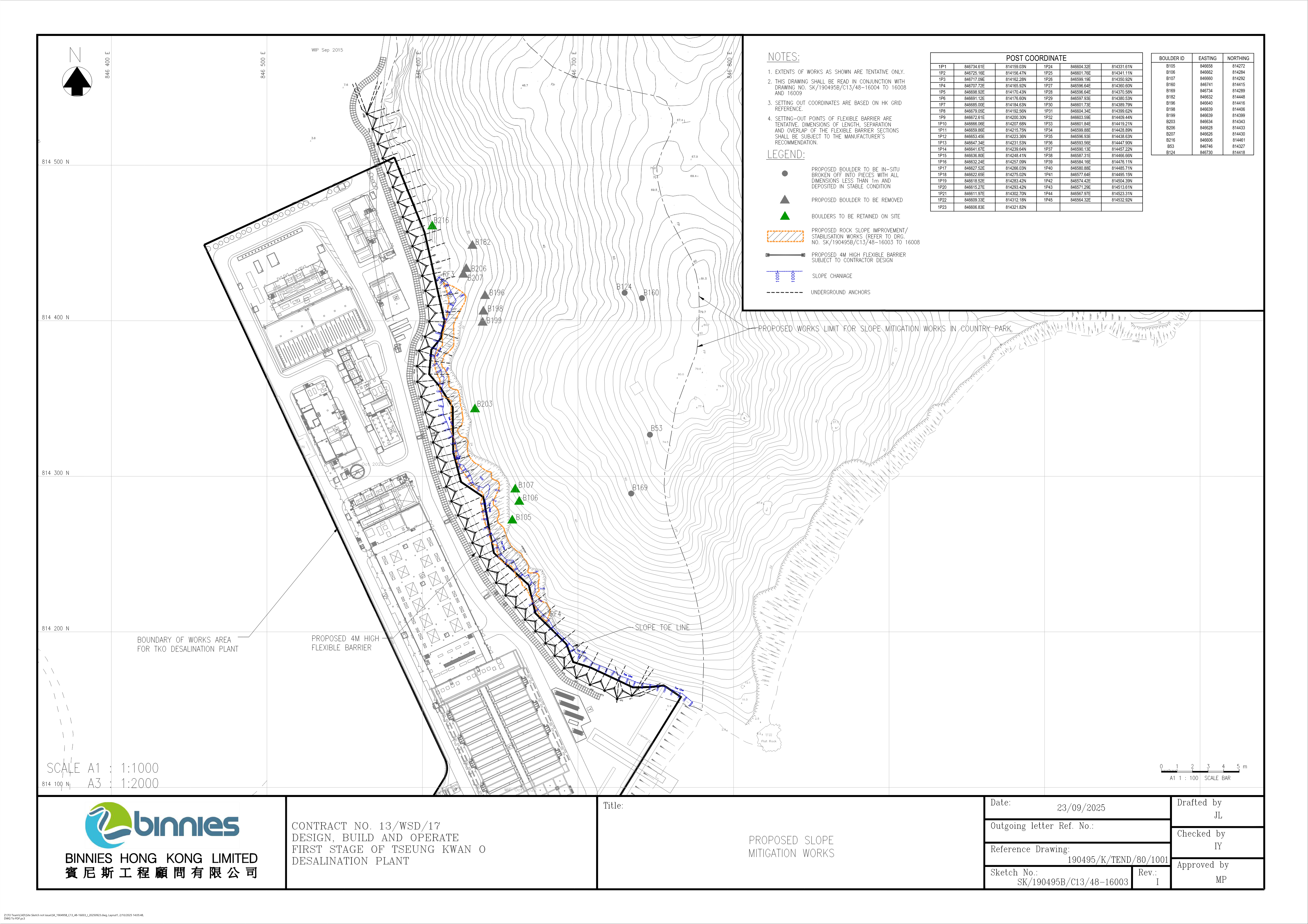
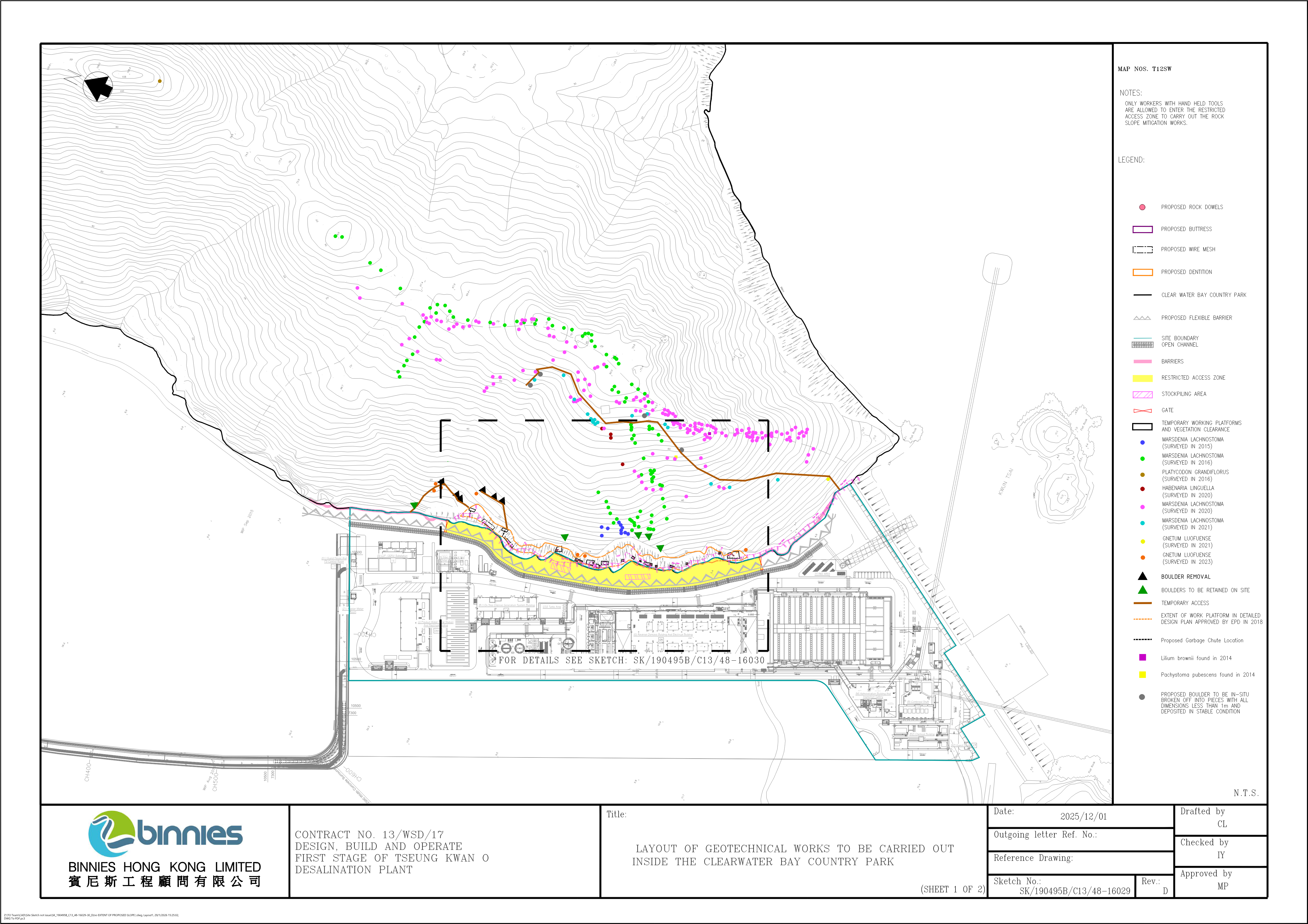
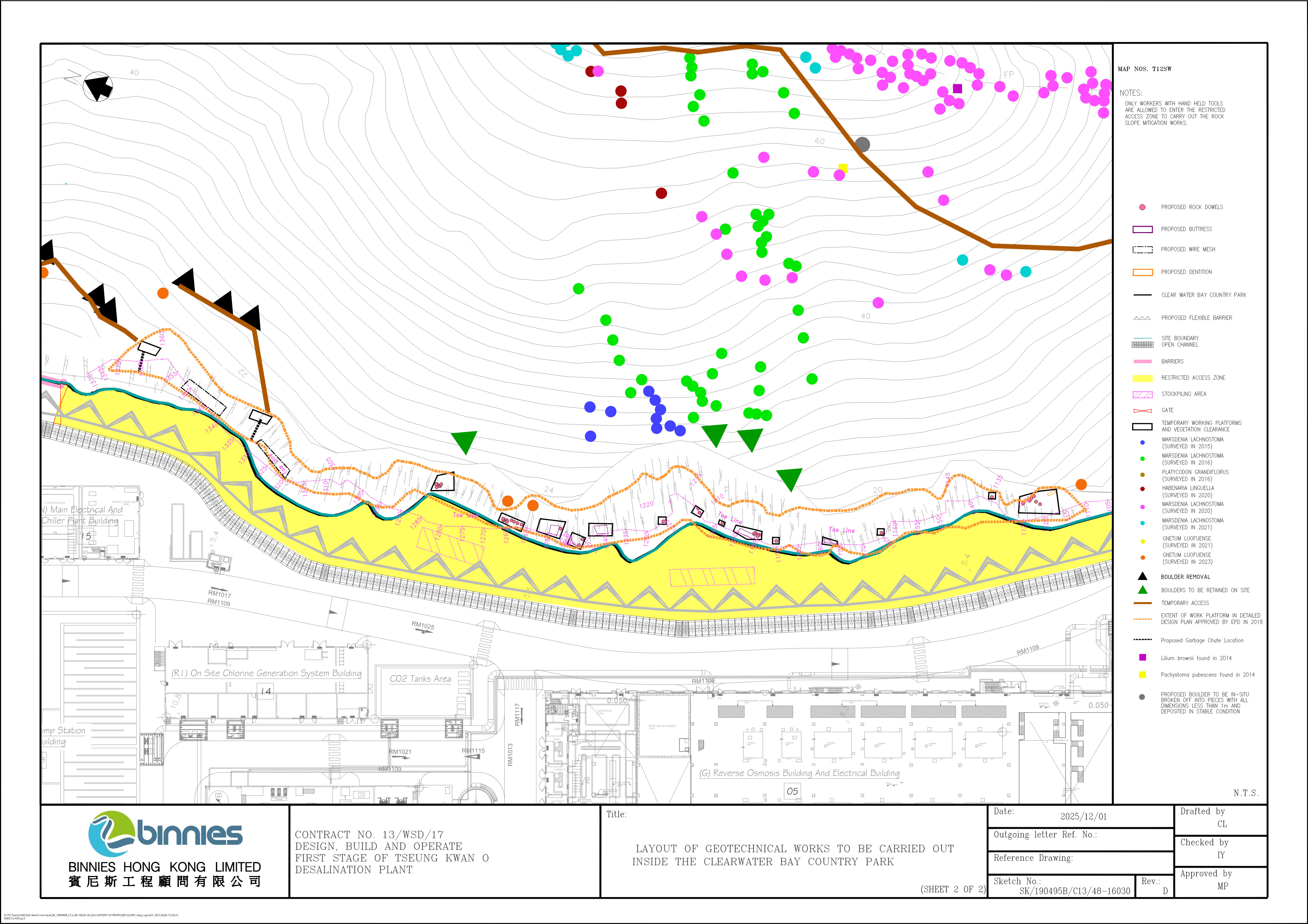
The Detailed Design Plan Slope Mitigation Works submitted under EP Condition 2.8 have recommended protection/ mitigation measures to be implemented on site during the construction stage of this Project. All recommended protection/ mitigation measures shall be fully and properly implemented. No site clearance works for slope mitigation works of this Project shall be allowed prior to the completion of such protection/ mitigation works on site. The key slope mitigation measures are summarised below and present in Appendix H:
Flexible Barrier
The flexible barriers will be located away from the slope toe of the Clear Water Bay Country Park (CWBCP). All above-ground elements of the flexible barrier are all located outside the CWBCP.
Inclined underground anchors, installed 3-4m into rock, are required and may extend into CWBCP boundary. The maximum length of the underground anchors shall be 15m. No ecological impact on plant species of conservation importance and trees anticipated as inclined anchors would be installed into bedrock situated 3-4m below the ground level.
Rock Slope Stabilisation/ Improvement Works
Rock stabilisation works will be adjusted to ensure that no tree will be felled, and no plant species of conservation importance are affected. The anchorage for the temporary working platform and access routes will be designed to avoid the plant species of conservation importance.
Slope mitigation works have been adjusted to suit the existing slope conditions, including 180m2 of wire mesh, 37 nos. of rock dowels, 5 nos. of buttress and flexible barrier along the slope toe. To reinstate vegetation loss and disturbance resulting from slope stabilisation works, hydroseeding and planting of grasses and shrub seedlings undertaken at the flexible barriers which will locate at the ground level adjacent to the existing slope toe. Regular monitoring and appropriate maintenance works to be carried out for a 12-month establishment period to ensure successful vegetation recovery, green effect and diversity.
As stated in the detailed design plan for the slope mitigation works, the design of the buttress wall and the requirement for tree rings were to be confirmed following rock mapping and assessment of the specific site conditions. Upon completion of the rock mapping and site surveys, it has been verified that the proposed buttress walls are aligned with sufficient spatial separation from all existing trees. This clearance ensures that tree roots, natural growth, and trunk movement will not interfere with, or impose any load on, the wall structure.
Tree rings are normally required when structural elements are located close to trees and may encroach upon the root zone or trunk. As the buttress walls have been intentionally designed with adequate spatial separation with the existing trees, no physical conflict between the existing trees and buttress walls is expected. The protective function typically provided by tree rings is therefore inherently achieved through the spatial separation, and additional tree rings would not offer further benefit.
The adopted design provides both structural safety and protection of existing trees without the need of tree rings. In addition, stone facing has been applied to the buttress walls to reinstate the natural appearance of the slope, and the wire mesh on the rock face has been detailed with openings at tree locations to avoid obstruction.
Boulder Removal/ Break-off
There are 6 nos. of unstable boulders will be removed and 4 nos. of boulders to be break-off. A temporary working platform and a minimum access clearance of 600 mm around each boulder will be provided for the proposed boulder removal/break‑off works. To avoid direct conflict between the boulder removal and nearby plant species of conservation importance, protection zones/ works exclusion zones will be established at least 1.5 m radius from the identified plant species of conservation importance to preserve them on site.
The protection zones/ works exclusion zones will be established prior to site clearance and throughout the construction period to separate the identified protected plant individuals from the works.
The temporary working platform and temporary access will be designed to avoid anchorage on the plant species of conservation importance.
Detailed design of the slope mitigation measures at Clear Water Bay Country Park could be referred to Appendix H and Detailed Design Plan for Slope Mitigation Works.
(https://www.tkodesal.hk/images/bv_tko_data/data/file/DDPIssue%209_all_flatten.pdf)
3.5. LIGHTING ARRANGEMENT (MM8)
3.5.1. GENERAL
All lights provided in the construction site or the proposed desalination plant should have the following features to minimize light spill outside the contract area:
• The number of lighting should be kept minimum;
• The lux level should be designed just sufficient for safety purpose;
• Point light towards the Site to minimize light spill outside the contract boundary;
• Shielded with hood to prevent sky glow;
• High mounting light will have less spill light and glare;
• Aim light no greater than 70º;
Reference: Guidance Note 01/20 Guidance Notes for the Reduction of Obtrusive Light •
Where light has to be pointed upward, adjust the light direction to ensure no spillage outside the target.
Reference: Guidance Note 01/20 Guidance Notes for the Reduction of Obtrusive Light
3.5.2. GARDEN LIGHTS IN OPERATION PHASE
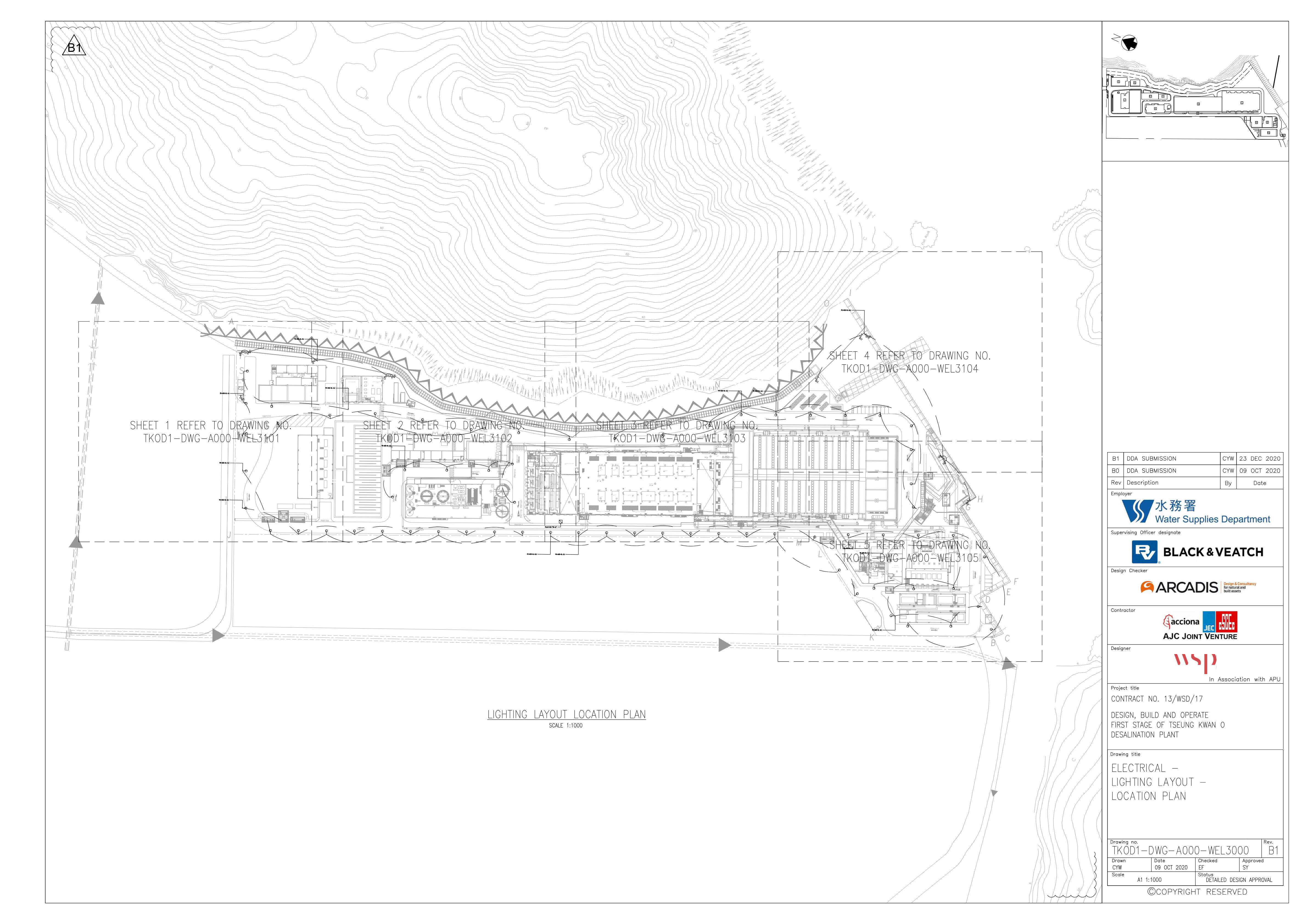
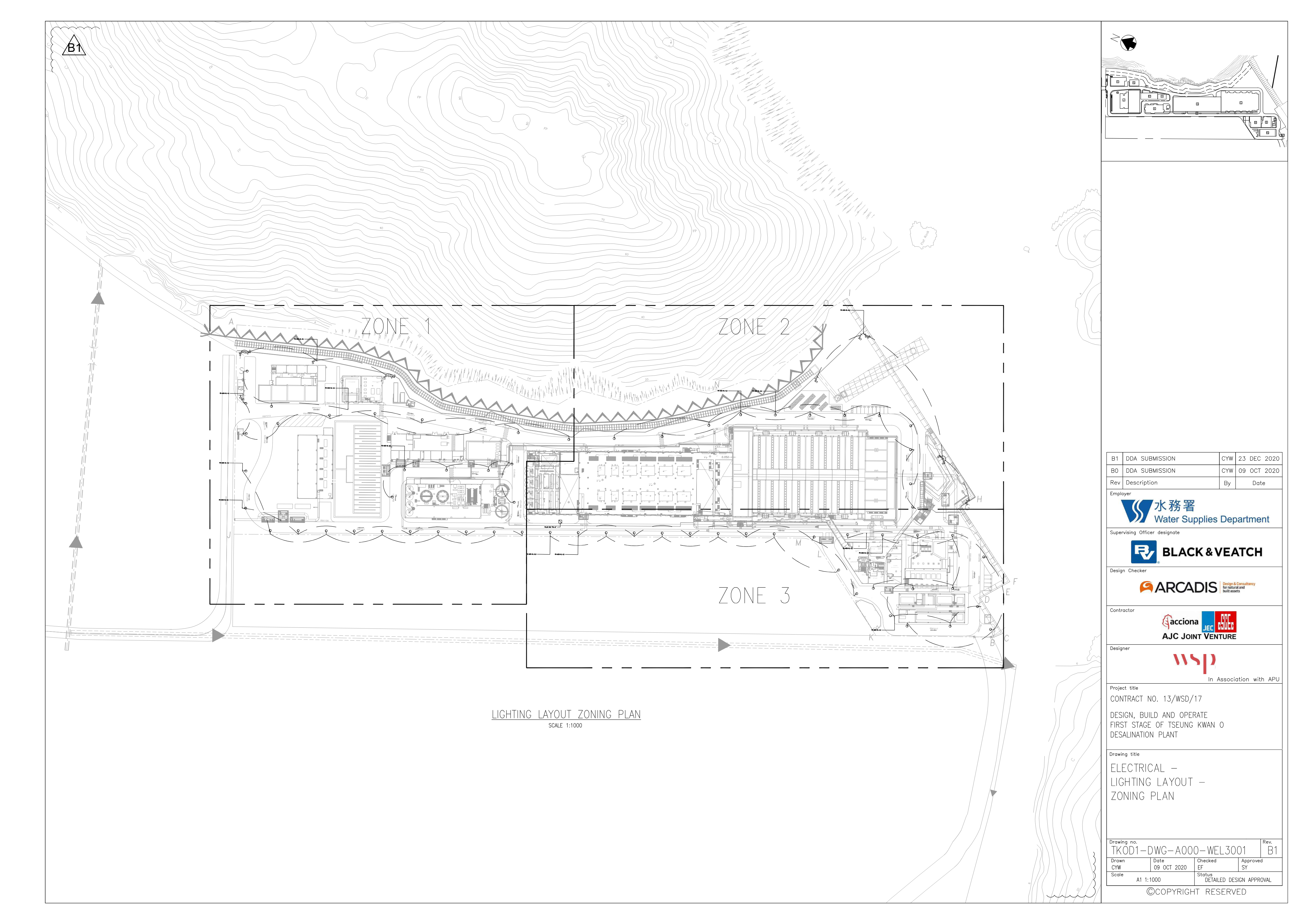
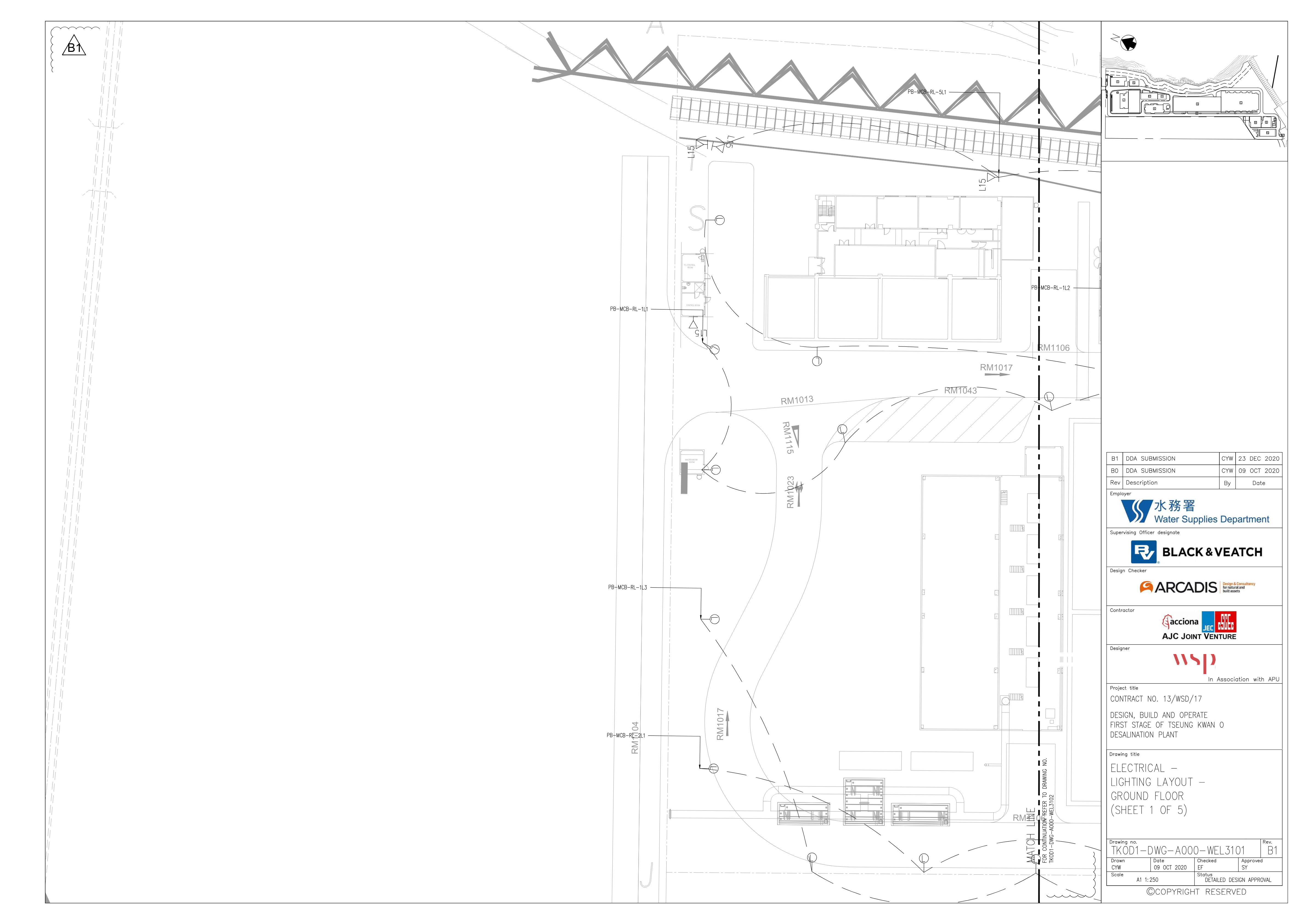
The outdoor landscape lighting system is crafted with LED bollard lighting along the pathway and spotlight implants to the landscape area will light up the entire garden at night-time that creates a fascinating foreground focal area. Bollard light with low lux level just enough for illuminating the garden will be adopted. The light will be diffused without pointing in one direction. The proposed lighting plan can be found in Appendix G.
4. TREE FELLING AND PRESERVATION PROPOSAL (MM4)
As described in Section 1, the project site for the proposed desalination plant was cleared of stockpiled C&D materials and vegetation by CEDD prior to site handover. Tree felling was carried out by CEDD in accordance with its approved tree‑felling application (LandsD approval memorandum ref. (30) in LM 2 to DLO/SK 651/SGS/59 Pt.6 dated 23 October 2018), and the site was handed over to WSD in December 2019. Following site handover, tree surveys were conducted in February and August 2020 within the DPTKO area and along the temporary access for boulder removal and stabilisation by break-off works to establish the baseline tree condition. LVMP Revision 7 presented the survey results for the DPTKO area only, while trees surveyed along the temporary access were not included.
The 2020 tree surveys identified that some trees originally proposed for felling under CEDD’s approved tree‑felling application had not been removed. These trees were subsequently felled by CEDD in 2020. In addition, the site was affected by typhoons and adverse weather conditions in the subsequent period. To confirm the updated baseline tree condition prior to commencement of construction works, further tree surveys were carried out in February, May and June 2022, and February 2023, covering the DPTKO area as well as the tree survey areas for rock slope stabilisation works, flexible barriers, and the temporary access for boulder removal and stabilisation by break-off works. LVMP Revision 8 updated the number of existing trees based on the available tree survey results but was limited to the DPTKO area. LVMP Revision 9 consolidates all tree survey data and presents a complete and up‑to‑date baseline tree inventory covering all project‑related works areas.
The LVMP was updated progressively to reflect changes in site conditions arising from additional tree felling works carried out by CEDD, tree impacts from adverse weather events, and the availability of updated tree survey data prior to commencement of construction works. LVMP Revision 9 was prepared to consolidate all available tree survey results and to ensure that the baseline tree inventory fully covers all project‑related works areas, including DPTKO, rock slope stabilisation works, flexible barriers, and temporary access areas. This update was necessary to ensure accuracy, completeness, and compliance with prevailing EIA and LVMP requirements.
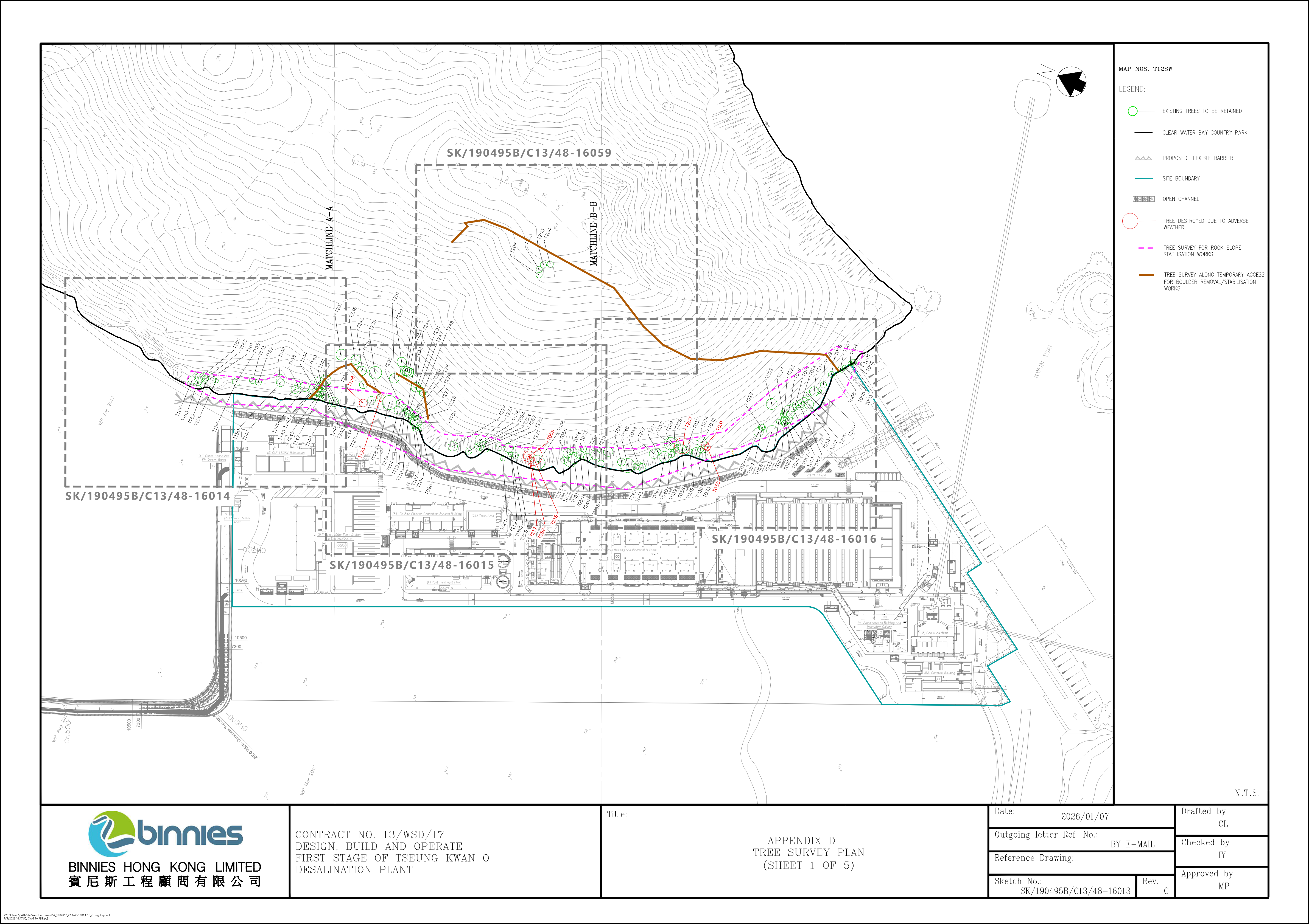
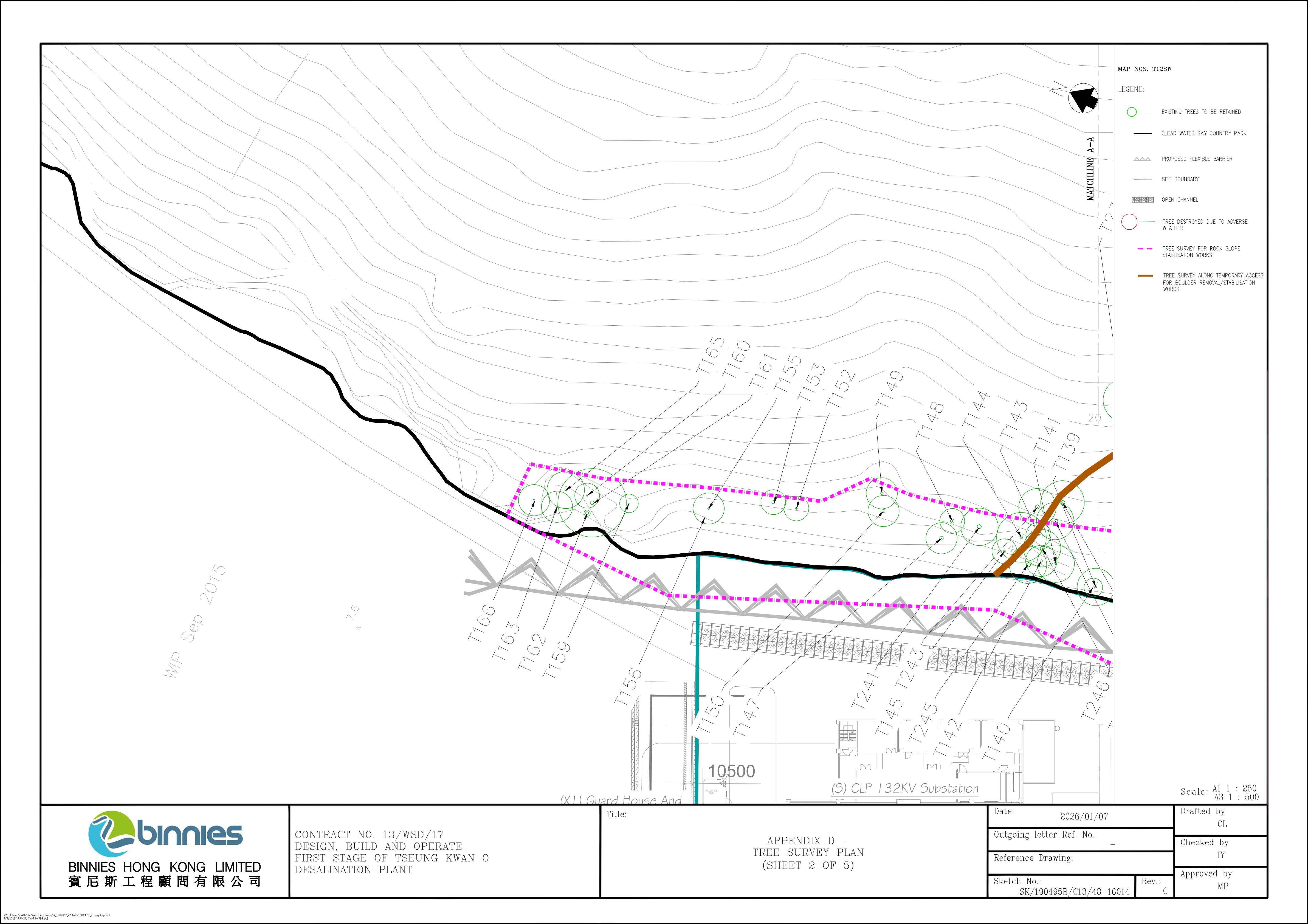
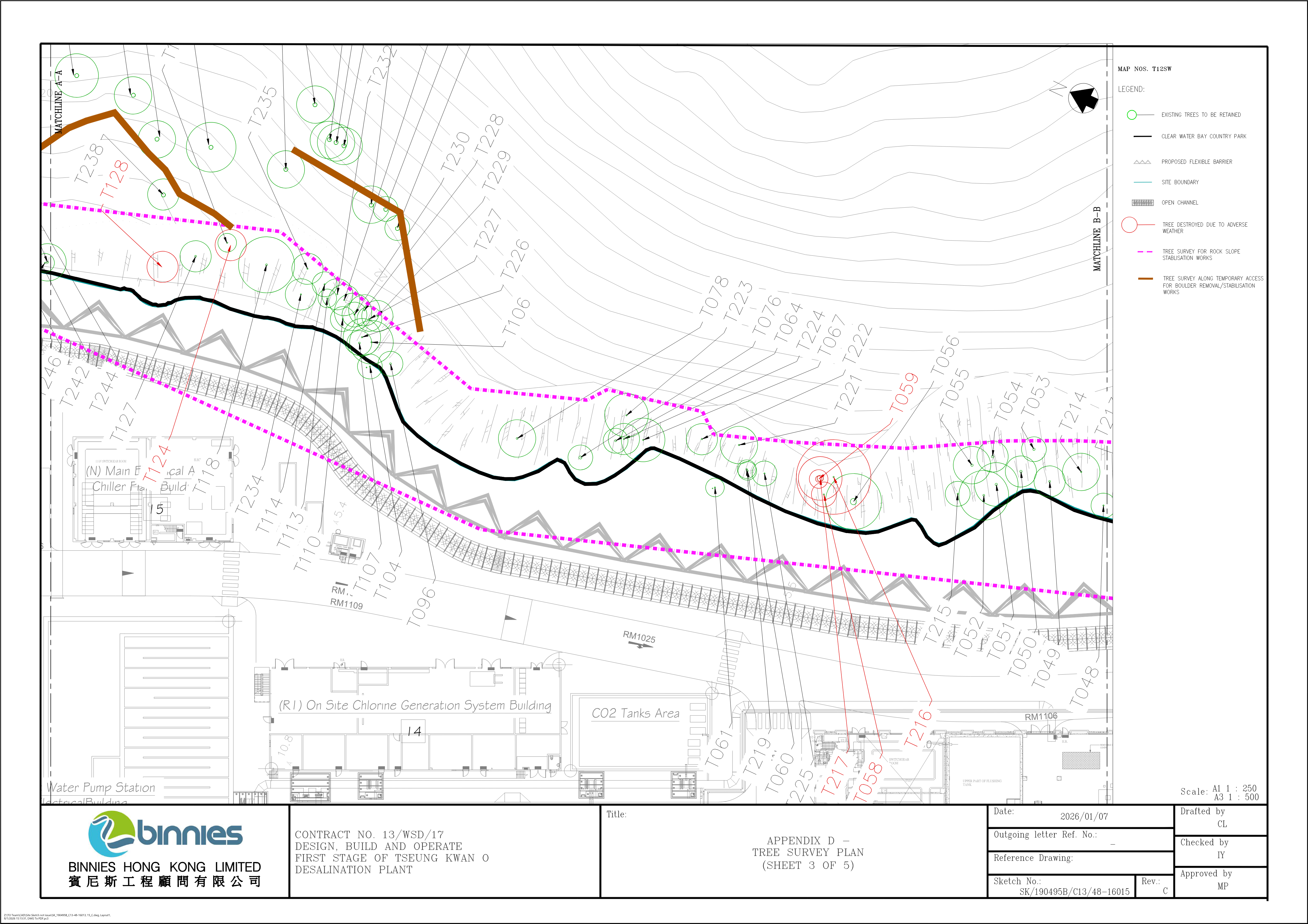
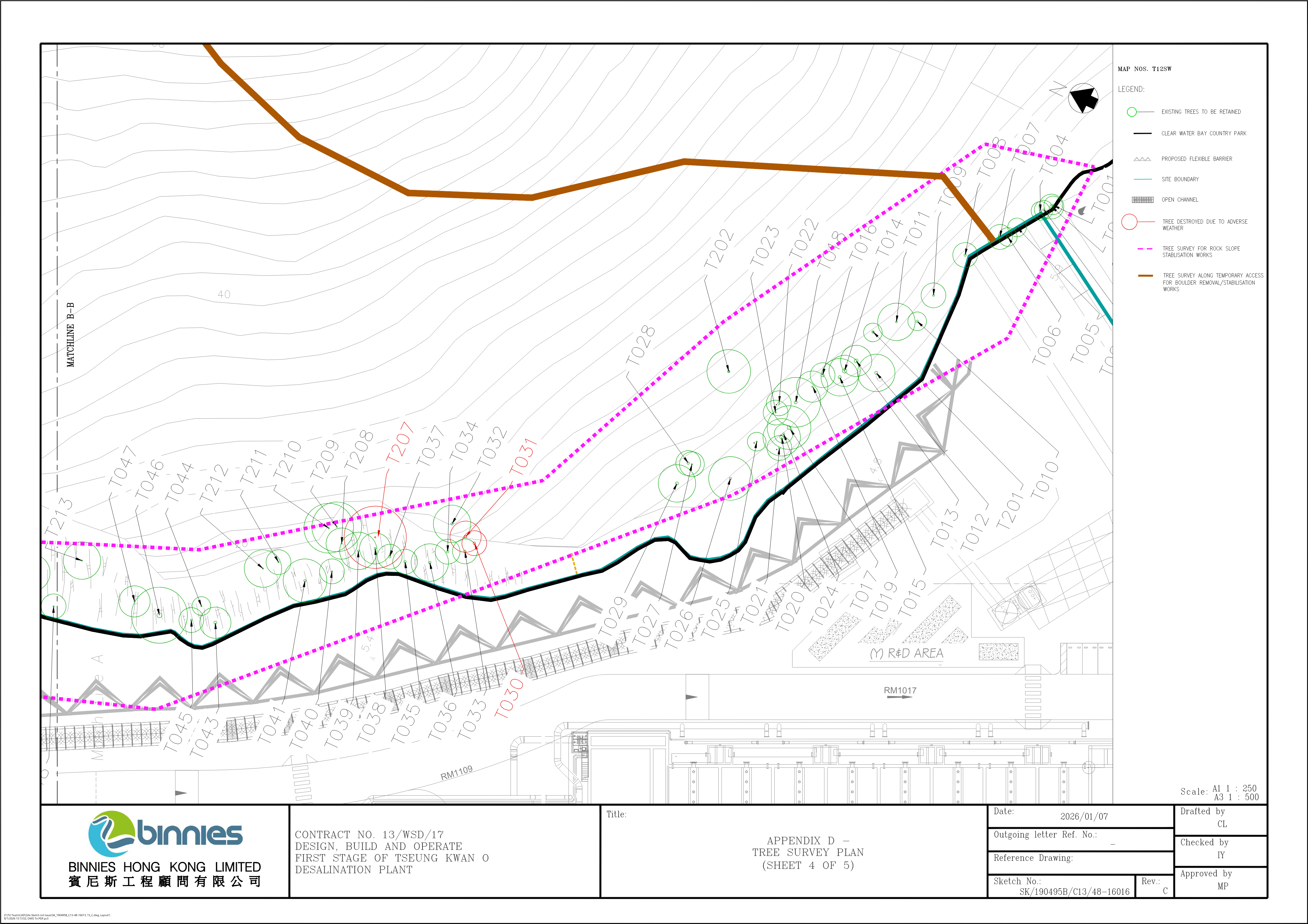
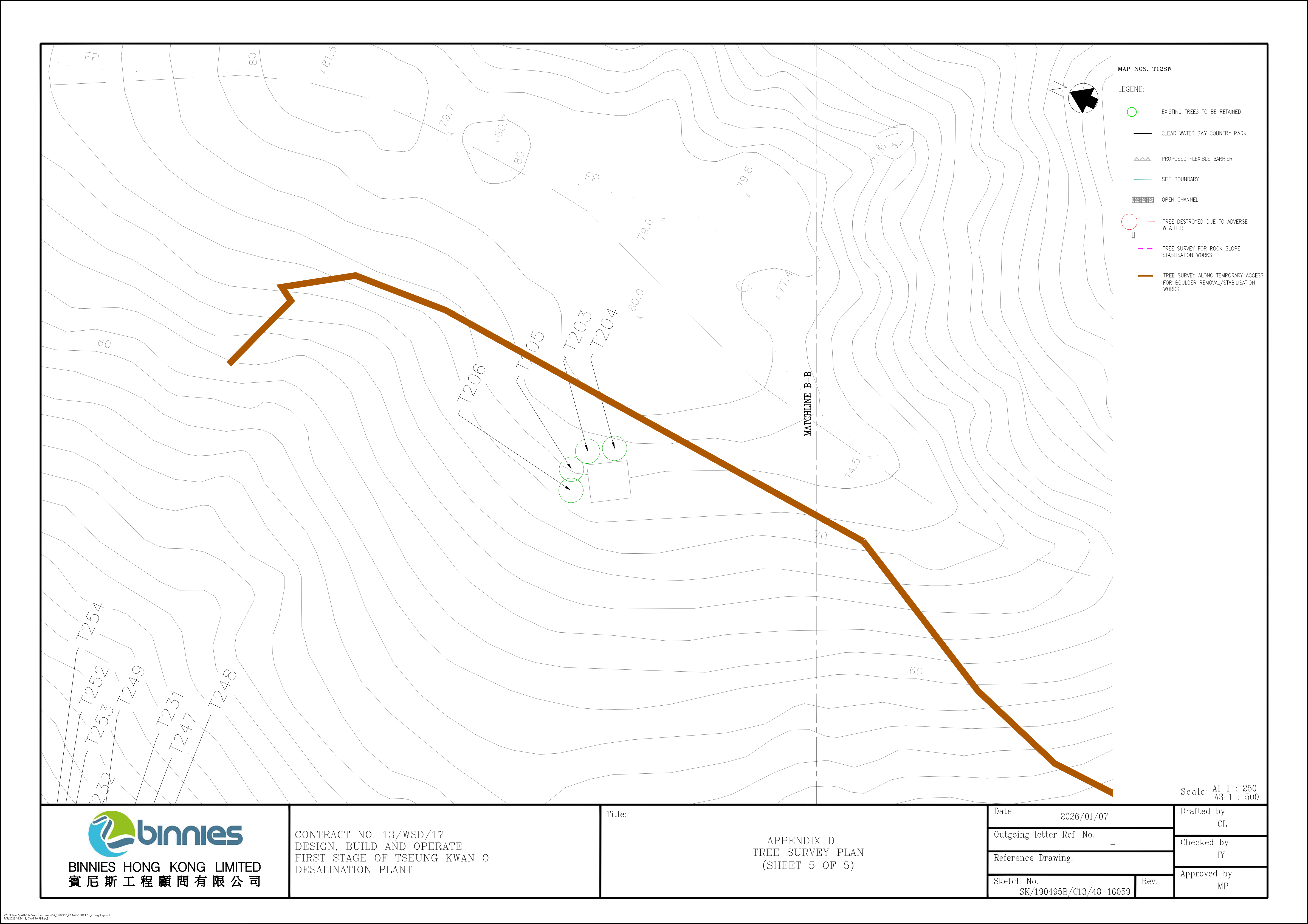
According to the tree surveys conducted in February and August 2020, February, May and June 2022, and February 2023, a total of 148 trees were recorded within the study area. Of these, three trees were located within the DPTKO area, while 145 trees were recorded within the tree survey areas for rock slope stabilisation works, flexible barriers, and along the temporary access for boulder removal and stabilisation by break-off works. All 148 trees were originally proposed for retention.
Following completion of the tree surveys, the site was affected by typhoons and adverse weather conditions, resulting in the collapse or loss of nine trees (i.e. T030, T031, T058, T059, T124, T128, T207, T216 and T217). Accordingly, a total of 139 existing trees are proposed for retention. The tree survey results are presented in Table 4.1 and Appendix B, while the tree treatment summary is provided in Table 4.2.
Table 4.1 Summary of Tree Survey Results
Scientific Name |
Chinese Name |
No. of tree(s) |
Acacia confusa |
台灣相思 |
6 |
Celtis sinensis |
朴樹 |
13 |
Ficus hispida |
對葉榕(牛乳樹) |
12 |
Ficus microcarpa |
細葉榕 |
4 |
Fiscus subpisocarpa |
筆管榕 |
5 |
Ficus variegata var. |
青果榕 |
1 |
Litsea glutinosa |
潺槁樹 |
1 |
Macaranga tanarius var. |
血桐 |
66 |
Mallotus paniculatus |
白楸 |
15 |
Peltophorum pterocarpum |
盾柱木(雙翼豆) |
1 |
Phoenix hanceana |
刺葵 |
2 |
Schefflrea heptaphylla |
鵝掌柴(鴨腳木) |
11 |
Sterculia lanceolata |
假蘋婆 |
9 |
Trema tomentosa (Roxb.) |
山黃痲 |
1 |
Leucaena leucocephala |
銀合歡 |
1 |
Total nos. of trees |
148 |
Table 4.2 Summary of Proposed Treatment to Existing Trees
Report record |
No. of tree(s) to be retained |
No. of tree(s) to be transplanted |
No. of tree(s) to be removed |
No. of tree(s) destroyed by adverse weather |
Total nos. of tree(s) |
Tree Survey |
148 |
0 |
0 |
9 |
139 |
5. CONSTRUCTION MITIGATION MEASURES
Located in the public filling area, the site is not visually attractive and looks similar to a construction site. Nevertheless, landscape and visual mitigation measures in construction phase are recommended as below:
5.1. BLENDING IN WITH THE EXISTING LANDSCAPE AND VISUAL
• Construction area and works shall be minimized to prevent affecting nearby landscape environment;
• Area of temporary structures, such as the contractor’s office, shall be minimized to a practical minimum and located at less visual prominent locations.
• Decorative hoarding with appropriate colours compatible with the surrounding area shall be erected around all works areas to minimize the visual impacts;
• Avoid potential impact on existing coastline and seashore
5.2. PROVIDING SOFT LANDSCAPING
• Exposed area and soil stockpiles shall be hydroseeded or covered with visually unobtrusive materials/ tarpaulins;
• Green roofs shall be considered on site office where possible;
• Commence landscape planting at locations where construction work has been completed.
5.3. CONSERVING/RECOVERING EXISTING GREENERY
• Existing trees near the Contract Boundary and slope mitigation work areas, and retained trees within site boundary shall be carefully protected. Detailed Tree Protection Specification shall be followed;
• The Contractor shall include a detailed working method statement for the protection of trees prior to conducting any works next to all retained trees;
• Trees unavoidably affected by the works shall be transplanted where practicable. Where possible, trees should be transplanted direct to permanent locations rather than temporary holding nurseries.
5.4. IMPLEMENTING GOOD SITE PRACTICES/ OTHER RECOMMENDED MITIGATION MEASURES
• Sufficient drainage system shall be provided to control run-off from entering the sea;
• All night-time lighting will be reduced to a practical minimum both in terms of number of units and lux level and will be hooded and directional (See Sec.3.4).
5.5. CONDUCTING REGULAR SITE AUDIT
• Site inspection shall be undertaken regularly to ensure mitigation measures are being effectively implemented;
• Coordinate implementation programme with concurrent contract, if any, to minimize potential cumulative impacts and where possible reduce the period of disturbance to visual context.
6. CONCLUSION
The landscape and visual mitigation measures to be implemented under Contract No. 13/WSD/17 have complied with the requirements and recommendations contained in the EIA Report (Register No. AEIAR-192/2015), the EP, the FEP and ERR. All measures recommended in this LVMP will be fully and properly implemented and maintained for the Contract.



Tree Survey Schedule
Project Title:
Date of Survey:
2020/0210. 2020/02/19, 2020/08/20, 2022/02/15, 2022/05/03, 2022/06/02
Tree No. |
Species |
Measurement |
Amenity value |
Form |
Health condition |
Structural condition |
Suitability for transplanting |
Conservation status |
Recommendation |
Department to provide expert advice to LandsD |
Additional Remarks |
|||||
Scientific name |
Chinese name |
height (m) |
DBH (mm) |
crown spread |
(high/medium/low) |
(good/average/poor) |
(high/medium/low) |
Remarks |
(retain/transplant/fell) |
|||||||
T001 |
Macaranga tanarius var. tomentosa |
血桐 |
5 |
240 |
3 |
Medium |
Average |
Average |
Average |
Low |
Near structure |
N/A |
Retain |
AFCD |
- |
|
T002 |
Macaranga tanarius var. tomentosa |
血桐 |
5 |
230 |
4 |
Medium |
Average |
Average |
Average |
Low |
Near structure |
N/A |
Retain |
AFCD |
- |
|
T003 |
Macaranga tanarius var. tomentosa |
血桐 |
4 |
140 |
3 |
Low |
Poor |
Average |
Average |
Low |
Poor form |
N/A |
Retain |
AFCD |
Bark crack |
|
T004 |
Macaranga tanarius var. tomentosa |
血桐 |
3 |
165 |
3 |
Low |
Poor |
Average |
Average |
Low |
Poor form |
N/A |
Retain |
AFCD |
Leaning |
|
T005 |
Macaranga tanarius var. tomentosa |
血桐 |
3 |
130 |
3 |
Low |
Poor |
Average |
Average |
Low |
Poor form |
N/A |
Retain |
AFCD |
Leaning |
|
T006 |
Macaranga tanarius var. tomentosa |
血桐 |
4 |
140 |
3 |
Medium |
Average |
Average |
Average |
Medium |
- |
N/A |
Retain |
AFCD |
- |
|
T007 |
Macaranga tanarius var. tomentosa |
血桐 |
5 |
200 |
4 |
Medium |
Average |
Average |
Average |
Medium |
- |
N/A |
Retain |
AFCD |
- |
|
T008 |
Celtis sinensis |
朴樹 |
7 |
170 |
4 |
Medium |
Average |
Average |
Average |
Low |
On slope |
N/A |
Retain |
AFCD |
- |
|
T009 |
Sterculia lanceolata |
假蘋婆 |
5 |
130 |
4 |
Medium |
Average |
Average |
Average |
Low |
On slope |
N/A |
Retain |
AFCD |
- |
|
T010 |
Phoenix hanceana |
刺葵 |
4 |
240 |
3 |
Medium |
Average |
Average |
Average |
Low |
On slope |
N/A |
Retain |
AFCD |
- |
|
T011 |
Macaranga tanarius var. tomentosa |
血桐 |
5 |
150 |
6 |
Medium |
Average |
Average |
Average |
Low |
On slope |
N/A |
Retain |
AFCD |
- |
|
T012 |
Celtis sinensis |
朴樹 |
8 |
240 |
6 |
Medium |
Average |
Average |
Average |
Low |
On slope |
N/A |
Retain |
AFCD |
Cross branches |
|
T013 |
Ficus hispida |
對葉榕(牛乳樹) |
5 |
289 |
5 |
Low |
Poor |
Average |
Average |
Low |
On slope |
N/A |
Retain |
AFCD |
Multiple trunks |
|
T014 |
Macaranga tanarius var. tomentosa |
血桐 |
6 |
180 |
5 |
Low |
Poor |
Average |
Average |
Low |
On slope |
N/A |
Retain |
AFCD |
- |
|
T015 |
Macaranga tanarius var. tomentosa |
血桐 |
6 |
191 |
6 |
Medium |
Average |
Average |
Average |
Low |
On slope |
N/A |
Retain |
AFCD |
Codominant trunks |
|
T016 |
Phoenix hanceana |
刺葵 |
4 |
285 |
4 |
Medium |
Average |
Average |
Average |
Low |
On slope |
N/A |
Retain |
AFCD |
- |
|
T017 |
Macaranga tanarius var. tomentosa |
血桐 |
6 |
150 |
5 |
Medium |
Average |
Poor |
Average |
Low |
On slope |
N/A |
Retain |
AFCD |
- |
|
T018 |
Macaranga tanarius var. tomentosa |
血桐 |
7 |
300 |
8 |
Medium |
Average |
Average |
Average |
Low |
On slope |
N/A |
Retain |
AFCD |
Broken branch, Exposed dead wood on trunk |
|
T019 |
Celtis sinensis |
朴樹 |
9 |
297 |
7 |
Medium |
Average |
Average |
Average |
Low |
On slope |
N/A |
Retain |
AFCD |
Codominant trunks |
|
T020 |
Celtis sinensis |
朴樹 |
9 |
250 |
6 |
Medium |
Average |
Average |
Average |
Low |
On slope |
N/A |
Retain |
AFCD |
- |
|
T021 |
Macaranga tanarius var. tomentosa |
血桐 |
6 |
140 |
4 |
Medium |
Average |
Average |
Average |
Low |
On slope |
N/A |
Retain |
AFCD |
Broken branch |
|
T022 |
Macaranga tanarius var. tomentosa |
血桐 |
5 |
170 |
4 |
Medium |
Average |
Average |
Average |
Low |
On slope |
N/A |
Retain |
AFCD |
- |
|
T023 |
Litsea glutinosa |
潺槁樹 |
5 |
140 |
4 |
Medium |
Average |
Poor |
Average |
Low |
On slope |
N/A |
Retain |
AFCD |
- |
|
T024 |
Macaranga tanarius var. tomentosa |
血桐 |
5 |
130 |
3 |
Medium |
Average |
Average |
Average |
Low |
On slope |
N/A |
Retain |
AFCD |
- |
|
T025 |
Macaranga tanarius var. tomentosa |
血桐 |
5 |
120 |
3 |
Medium |
Average |
Average |
Average |
Low |
On slope |
N/A |
Retain |
AFCD |
- |
|
T026 |
Macaranga tanarius var. tomentosa |
血桐 |
9 |
240 |
7 |
Medium |
Average |
Poor |
Poor |
Low |
On slope |
N/A |
Retain |
AFCD |
Codominant branches, dead tree |
|
T027 |
Celtis sinensis |
朴樹 |
6 |
140 |
4 |
Medium |
Average |
Average |
Average |
Low |
On slope |
N/A |
Retain |
AFCD |
- |
|
T028 |
Macaranga tanarius var. tomentosa |
血桐 |
6 |
180 |
4 |
Medium |
Average |
Poor |
Average |
Low |
On slope |
N/A |
Retain |
AFCD |
- |
|
T029 |
Macaranga tanarius var. tomentosa |
血桐 |
7 |
220 |
6 |
Medium |
Average |
Average |
Average |
Low |
On slope |
N/A |
Retain |
AFCD |
- |
|
T030 |
Macaranga tanarius var. tomentosa |
血桐 |
4 |
95 |
4 |
Low |
Poor |
Average |
Average |
Low |
On slope |
N/A |
Retain |
AFCD |
Destroyed by adverse weather |
|
T031 |
Celtis sinensis |
朴樹 |
7 |
140 |
5 |
Medium |
Average |
Average |
Average |
Low |
On slope |
N/A |
Retain |
AFCD |
Destroyed by adverse weather |
|
T032 |
Ficus subpisocarpa |
筆管榕 |
7 |
230 |
6 |
Medium |
Average |
Average |
Average |
Low |
On slope |
N/A |
Retain |
AFCD |
- |
|
T033 |
Sterculia lanceolata |
假蘋婆 |
6 |
130 |
4 |
Medium |
Average |
Average |
Average |
Low |
On slope |
N/A |
Retain |
AFCD |
- |
|
T034 |
Ficus subpisocarpa |
筆管榕 |
6 |
120 |
4 |
Medium |
Average |
Average |
Average |
Low |
On slope |
N/A |
Retain |
AFCD |
- |
|
T035 |
Sterculia lanceolata |
假蘋婆 |
5 |
150 |
4 |
Medium |
Average |
Average |
Average |
Low |
On slope |
N/A |
Retain |
AFCD |
Codominant branches |
Tree Survey Schedule
Project Title:
Date of Survey:
2020/0210. 2020/02/19, 2020/08/20, 2022/02/15, 2022/05/03, 2022/06/02
Tree No. |
Species |
Measurement |
Amenity value |
Form |
Health condition |
Structural condition |
Suitability for transplanting |
Conservation status |
Recommendation |
Department to provide expert advice to LandsD |
Additional Remarks |
|||||
Scientific name |
Chinese name |
height (m) |
DBH (mm) |
crown spread |
(high/medium/low) |
(good/average/poor) |
(high/medium/low) |
Remarks |
(retain/transplant/fell) |
|||||||
T036 |
Macaranga tanarius var. tomentosa |
血桐 |
7 |
180 |
6 |
Medium |
Average |
Average |
Average |
Low |
On slope |
N/A |
Retain |
AFCD |
- |
|
T037 |
Ficus hispida |
對葉榕(牛乳樹) |
7 |
140 |
4 |
Medium |
Average |
Average |
Average |
Low |
On slope |
N/A |
Retain |
AFCD |
Codominant branches |
|
T038 |
Macaranga tanarius var. tomentosa |
血桐 |
7 |
155 |
5 |
Medium |
Average |
Average |
Average |
Low |
On slope |
N/A |
Retain |
AFCD |
- |
|
T039 |
Macaranga tanarius var. tomentosa |
血桐 |
8 |
160 |
6 |
Medium |
Average |
Average |
Average |
Low |
On slope |
N/A |
Retain |
AFCD |
- |
|
T040 |
Macaranga tanarius var. tomentosa |
血桐 |
7 |
130 |
4 |
Medium |
Average |
Average |
Average |
Low |
On slope |
N/A |
Retain |
AFCD |
- |
|
T041 |
Acacia confusa |
台灣相思 |
10 |
150 |
7 |
Medium |
Poor |
Average |
Poor |
Low |
On slope |
N/A |
Retain |
AFCD |
Root-plate movement |
|
T043 |
Ficus subpisocarpa |
筆管榕 |
5 |
200 |
5 |
Medium |
Average |
Average |
Average |
Low |
On slope |
N/A |
Retain |
AFCD |
- |
|
T044 |
Ficus hispida |
對葉榕(牛乳樹) |
5 |
163 |
3 |
Medium |
Average |
Average |
Average |
Low |
On slope |
N/A |
Retain |
AFCD |
Codominant trunks |
|
T045 |
Macaranga tanarius var. tomentosa |
血桐 |
6 |
150 |
4 |
Medium |
Average |
Average |
Average |
Low |
On slope |
N/A |
Retain |
AFCD |
Leaning |
|
T046 |
Ficus microcarpa |
榕樹(細葉榕) |
11 |
420 |
9 |
Medium |
Average |
Average |
Average |
Low |
On slope |
N/A |
Retain |
AFCD |
Codominant branches |
|
T047 |
Ficus hispida |
對葉榕(牛乳樹) |
5 |
198 |
5 |
Medium |
Average |
Average |
Average |
Low |
On slope |
N/A |
Retain |
AFCD |
Codominant trunks |
|
T048 |
Ficus microcarpa |
榕樹(細葉榕) |
5 |
197 |
4 |
Low |
Poor |
Average |
Average |
Low |
On slope |
N/A |
Retain |
AFCD |
Multiple trunks |
|
T049 |
Macaranga tanarius var. tomentosa |
血桐 |
6 |
212 |
5 |
Medium |
Average |
Poor |
Average |
Low |
On slope |
N/A |
Retain |
AFCD |
Codominant trunks |
|
T050 |
Macaranga tanarius var. tomentosa |
血桐 |
7 |
180 |
5 |
Low |
Poor |
Average |
Average |
Low |
On slope |
N/A |
Retain |
AFCD |
Leaning |
|
T051 |
Macaranga tanarius var. tomentosa |
血桐 |
8 |
180 |
7 |
Medium |
Average |
Average |
Average |
Low |
On slope |
N/A |
Retain |
AFCD |
- |
|
T052 |
Ficus subpisocarpa |
筆管榕 |
8 |
264 |
8 |
Medium |
Average |
Average |
Average |
Low |
On slope |
N/A |
Retain |
AFCD |
- |
|
T053 |
Ficus hispida |
對葉榕(牛乳樹) |
6 |
140 |
4 |
Medium |
Average |
Average |
Average |
Low |
On slope |
N/A |
Retain |
AFCD |
- |
|
T054 |
Macaranga tanarius var. tomentosa |
血桐 |
6 |
160 |
5 |
Medium |
Average |
Average |
Average |
Low |
On slope |
N/A |
Retain |
AFCD |
Codominant branches |
|
T055 |
Macaranga tanarius var. tomentosa |
血桐 |
8 |
244 |
6 |
Medium |
Average |
Average |
Average |
Low |
On slope |
N/A |
Retain |
AFCD |
Codominant trunks |
|
T056 |
Ficus microcarpa |
榕樹(細葉榕) |
10 |
407 |
9 |
Medium |
Average |
Average |
Average |
Low |
On slope |
N/A |
Retain |
AFCD |
Multiple trunks |
|
T058 |
Macaranga tanarius var. tomentosa |
血桐 |
6 |
196 |
4 |
Low |
Poor |
Poor |
Average |
Low |
On slope |
N/A |
Retain |
AFCD |
Climber Destroyed by adverse weather |
|
T059 |
Macaranga tanarius var. tomentosa |
血桐 |
6 |
120 |
3 |
Low |
Poor |
Average |
Average |
Low |
On slope |
N/A |
Retain |
AFCD |
Destroyed by adverse weather |
|
T060 |
Macaranga tanarius var. tomentosa |
血桐 |
6 |
149 |
3 |
Low |
Poor |
Average |
Average |
Low |
On slope |
N/A |
Retain |
AFCD |
Leaning |
|
T061 |
Mallotus paniculatus |
白楸 |
5 |
130 |
3 |
Medium |
Average |
Average |
Average |
Low |
On slope |
N/A |
Retain |
WSD |
- |
|
T064 |
Macaranga tanarius var. tomentosa |
血桐 |
8 |
135 |
4 |
Medium |
Average |
Average |
Average |
Low |
On slope |
N/A |
Retain |
AFCD |
- |
|
T067 |
Macaranga tanarius var. tomentosa |
血桐 |
7 |
185 |
7 |
Medium |
Average |
Average |
Average |
Low |
On slope |
N/A |
Retain |
AFCD |
- |
|
T076 |
Ficus microcarpa |
榕樹(細葉榕) |
5 |
120 |
4 |
Medium |
Average |
Average |
Average |
Low |
On slope |
N/A |
Retain |
AFCD |
- |
|
T078 |
Macaranga tanarius var. tomentosa |
血桐 |
7 |
160 |
6 |
Medium |
Average |
Average |
Average |
Low |
On slope |
N/A |
Retain |
AFCD |
- |
|
T096 |
Macaranga tanarius var. tomentosa |
血桐 |
7 |
150 |
4 |
Low |
Poor |
Average |
Poor |
Low |
On slope |
N/A |
Retain |
AFCD |
Trunk wound |
|
T104 |
Sterculia lanceolata |
假蘋婆 |
6 |
105 |
4 |
Medium |
Average |
Average |
Average |
Medium |
- |
N/A |
Retain |
WSD |
- |
|
T106 |
Macaranga tanarius var. tomentosa |
血桐 |
7 |
259 |
7 |
Low |
Poor |
Average |
Average |
Low |
On slope |
N/A |
Retain |
AFCD |
Multiple trunks |
|
T107 |
Macaranga tanarius var. tomentosa |
血桐 |
5 |
170 |
4 |
Low |
Poor |
Average |
Average |
Low |
On slope |
N/A |
Retain |
AFCD |
Leaning |
|
T110 |
Macaranga tanarius var. tomentosa |
血桐 |
6 |
198 |
4 |
Medium |
Poor |
Average |
Poor |
Low |
On slope |
N/A |
Retain |
AFCD |
Leaning |
|
T113 |
Sterculia lanceolata |
假蘋婆 |
7 |
100 |
3 |
Medium |
Average |
Average |
Average |
Low |
On slope |
N/A |
Retain |
AFCD |
- |
|
T114 |
Ficus hispida |
對葉榕(牛乳樹) |
6 |
160 |
4 |
Medium |
Average |
Average |
Average |
Low |
On slope |
N/A |
Retain |
AFCD |
- |
Tree Survey Schedule
Project Title:
Date of Survey:
2020/0210. 2020/02/19, 2020/08/20, 2022/02/15, 2022/05/03, 2022/06/02
Tree No. |
Species |
Measurement |
Amenity value |
Form |
Health condition |
Structural condition |
Suitability for transplanting |
Conservation status |
Recommendation |
Department to provide expert advice to LandsD |
Additional Remarks |
|||||
Scientific name |
Chinese name |
height (m) |
DBH (mm) |
crown spread |
(high/medium/low) |
(good/average/poor) |
(high/medium/low) |
Remarks |
(retain/transplant/fell) |
|||||||
T118 |
Macaranga tanarius var. tomentosa |
血桐 |
9 |
330 |
9 |
Medium |
Poor |
Average |
Poor |
Low |
On slope |
N/A |
Retain |
AFCD |
Root-plate movement |
|
T124 |
Macaranga tanarius var. tomentosa |
血桐 |
6 |
140 |
5 |
Medium |
Average |
Average |
Average |
Low |
On slope |
N/A |
Retain |
AFCD |
Destroyed by adverse weather |
|
T125 |
Macaranga tanarius var. tomentosa |
血桐 |
5 |
100 |
3 |
Medium |
Average |
Average |
Average |
Low |
On slope |
N/A |
Retain |
AFCD |
- |
|
T127 |
Ficus hispida |
對葉榕(牛乳樹) |
7 |
200 |
5 |
Medium |
Average |
Average |
Average |
Low |
On slope |
N/A |
Retain |
AFCD |
Bark crack |
|
T128 |
Macaranga tanarius var. tomentosa |
血桐 |
6 |
140 |
5 |
Medium |
Average |
Average |
Average |
Low |
On slope |
N/A |
Retain |
AFCD |
Destroyed by adverse weather |
|
T139 |
Macaranga tanarius var. tomentosa |
血桐 |
9 |
180 |
6 |
Medium |
Average |
Average |
Average |
Medium |
- |
N/A |
Retain |
AFCD |
- |
|
T140 |
Macaranga tanarius var. tomentosa |
血桐 |
5 |
100 |
3 |
Medium |
Average |
Average |
Average |
Medium |
- |
N/A |
Retain |
AFCD |
- |
|
T141 |
Macaranga tanarius var. tomentosa |
血桐 |
8 |
180 |
6 |
Medium |
Average |
Average |
Average |
Low |
On slope |
N/A |
Retain |
AFCD |
- |
|
T142 |
Macaranga tanarius var. tomentosa |
血桐 |
7 |
230 |
5 |
Medium |
Average |
Average |
Average |
Low |
On slope |
N/A |
Retain |
AFCD |
Abnormal bark crack |
|
T143 |
Ficus hispida |
對葉榕(牛乳樹) |
6 |
170 |
4 |
Medium |
Average |
Average |
Average |
Low |
On slope |
N/A |
Retain |
AFCD |
- |
|
T144 |
Macaranga tanarius var. tomentosa |
血桐 |
7 |
240 |
8 |
Medium |
Average |
Average |
Average |
Low |
On slope |
N/A |
Retain |
AFCD |
- |
|
T145 |
Ficus hispida |
對葉榕(牛乳樹) |
5 |
150 |
4 |
Medium |
Average |
Average |
Average |
Low |
On slope |
N/A |
Retain |
AFCD |
- |
|
T147 |
Macaranga tanarius var. tomentosa |
血桐 |
8 |
330 |
5 |
Medium |
Average |
Average |
Average |
Low |
On slope |
N/A |
Retain |
AFCD |
- |
|
T148 |
Ficus hispida |
對葉榕(牛乳樹) |
6 |
190 |
4 |
Low |
Poor |
Poor |
Average |
Low |
On slope |
N/A |
Retain |
AFCD |
Climber, Old termite track |
|
T149 |
Macaranga tanarius var. tomentosa |
血桐 |
7 |
260 |
5 |
Medium |
Average |
Average |
Average |
Low |
On slope |
N/A |
Retain |
AFCD |
- |
|
T150 |
Macaranga tanarius var. tomentosa |
血桐 |
7 |
360 |
5 |
Low |
Poor |
Poor |
Poor |
Low |
- |
N/A |
Retain |
AFCD |
Abnormal bark crack, dead branch, exposed dead wood |
|
T152 |
Sterculia lanceolata |
假蘋婆 |
7 |
210 |
4 |
Medium |
Average |
Average |
Average |
Low |
On slope |
N/A |
Retain |
AFCD |
- |
|
T153 |
Sterculia lanceolata |
假蘋婆 |
7 |
280 |
4 |
Medium |
Average |
Average |
Average |
Low |
On slope |
N/A |
Retain |
AFCD |
Multiple trunks |
|
T155 |
Mallotus paniculatus |
白楸 |
7 |
220 |
5 |
Medium |
Average |
Average |
Average |
Low |
On slope |
N/A |
Retain |
AFCD |
- |
|
T156 |
Celtis sinensis |
朴樹 |
4 |
95 |
3 |
Medium |
Average |
Average |
Average |
Medium |
- |
N/A |
Retain |
AFCD |
- |
|
T159 |
Mallotus paniculatus |
白楸 |
5 |
95 |
3 |
Medium |
Average |
Average |
Average |
Low |
On slope |
N/A |
Retain |
AFCD |
- |
|
T160 |
Celtis sinensis |
朴樹 |
4 |
120 |
4 |
Medium |
Average |
Average |
Average |
Low |
On slope |
N/A |
Retain |
AFCD |
- |
|
T161 |
Acacia confusa |
台灣相思 |
12 |
500 |
11 |
Medium |
Average |
Average |
Average |
Low |
On slope |
N/A |
Retain |
AFCD |
Codominant trunk |
|
T162 |
Acacia confusa |
台灣相思 |
4 |
240 |
1 |
Low |
Poor |
Poor |
Poor |
Low |
On slope |
N/A |
Retain |
AFCD |
Topped, decay |
|
T163 |
Acacia confusa |
台灣相思 |
10 |
170 |
5 |
Medium |
Average |
Average |
Average |
Low |
On slope |
N/A |
Retain |
AFCD |
Decay |
|
T165 |
Macaranga tanarius var. tomentosa |
血桐 |
7 |
210 |
6 |
Medium |
Average |
Average |
Average |
Low |
On slope |
N/A |
Retain |
AFCD |
- |
|
T166 |
Celtis sinensis |
朴樹 |
8 |
210 |
5 |
Medium |
Average |
Average |
Average |
Low |
On slope |
N/A |
Retain |
AFCD |
- |
|
T201 |
Acacia confusa |
台灣相思 |
4 |
110 |
3 |
Medium |
Average |
Average |
Average |
Low |
On slope |
N/A |
Retain |
AFCD |
- |
|
T202 |
Peltophorum pterocarpum |
盾柱木(雙翼豆) |
10 |
398 |
7 |
Medium |
Average |
Average |
Average |
Low |
On slope |
N/A |
Retain |
AFCD |
- |
|
T203 |
Celtis sinensis |
朴樹 |
7 |
240 |
7 |
Medium |
Average |
Average |
Average |
Low |
On slope |
N/A |
Retain |
AFCD |
- |
|
T204 |
Schefflera heptaphylla |
鵝掌柴(鴨腳木) |
4 |
145 |
3 |
Medium |
Average |
Average |
Average |
Low |
On slope |
N/A |
Retain |
AFCD |
- |
|
T205 |
Celtis sinensis |
朴樹 |
7 |
230 |
5 |
Medium |
Average |
Average |
Average |
Low |
On slope |
N/A |
Retain |
AFCD |
Climber |
|
T206 |
Celtis sinensis |
朴樹 |
7 |
198 |
5 |
Medium |
Average |
Average |
Average |
Low |
On slope |
N/A |
Retain |
AFCD |
Climber |
|
T207 |
Macaranga tanarius var. tomentosa |
血桐 |
8 |
230 |
10 |
Medium |
Average |
Average |
Average |
Low |
On slope |
N/A |
Retain |
AFCD |
Destroyed by adverse weather |
Tree Survey Schedule
Project Title:
Date of Survey:
2020/0210. 2020/02/19, 2020/08/20, 2022/02/15, 2022/05/03, 2022/06/02
Tree No. |
Species |
Measurement |
Amenity value |
Form |
Health condition |
Structural condition |
Suitability for transplanting |
Conservation status |
Recommendation |
Department to provide expert advice to LandsD |
Additional Remarks |
|||||
Scientific name |
Chinese name |
height (m) |
DBH (mm) |
crown spread |
(high/medium/low) |
(good/average/poor) |
(high/medium/low) |
Remarks |
(retain/transplant/fell) |
|||||||
T208 |
Ficus hispida |
對葉榕(牛乳樹) |
7 |
190 |
5 |
Medium |
Average |
Average |
Average |
Low |
On slope |
N/A |
Retain |
AFCD |
- |
|
T209 |
Schefflera heptaphylla |
鵝掌柴(鴨腳木) |
7 |
220 |
8 |
Medium |
Average |
Average |
Average |
Low |
On slope |
N/A |
Retain |
AFCD |
Codominant branches |
|
T210 |
Schefflera heptaphylla |
鵝掌柴(鴨腳木) |
8 |
225 |
8 |
Medium |
Average |
Average |
Average |
Low |
On slope |
N/A |
Retain |
AFCD |
- |
|
T211 |
Schefflera heptaphylla |
鵝掌柴(鴨腳木) |
5 |
110 |
4 |
Medium |
Average |
Average |
Average |
Low |
On slope |
N/A |
Retain |
AFCD |
- |
|
T212 |
Acacia confusa |
台灣相思 |
8 |
260 |
6 |
Medium |
Average |
Average |
Average |
Low |
On slope |
N/A |
Retain |
AFCD |
Codominant branches |
|
T213 |
Macaranga tanarius var. tomentosa |
血桐 |
6 |
110 |
6 |
Low |
Poor |
Average |
Poor |
Low |
On slope |
N/A |
Retain |
AFCD |
Leaning, exposed dead wood at trunk base |
|
T214 |
Macaranga tanarius var. tomentosa |
血桐 |
5 |
160 |
6 |
Low |
Poor |
Average |
Poor |
Low |
On slope |
N/A |
Retain |
AFCD |
Leaning |
|
T215 |
Trema tomentosa (Roxb.) H.Hara |
山黃麻 |
5 |
120 |
4 |
Medium |
Average |
Average |
Average |
Low |
On slope |
N/A |
Retain |
AFCD |
- |
|
T216 |
Ficus subpisocarpa |
筆管榕 |
11 |
468 |
12 |
Medium |
Average |
Average |
Average |
Low |
On slope |
N/A |
Retain |
AFCD |
Exposed root wound Destroyed by adverse weather |
|
T217 |
Schefflera heptaphylla |
鵝掌柴(鴨腳木) |
7 |
120 |
4 |
Medium |
Average |
Average |
Average |
Low |
On slope |
N/A |
Retain |
AFCD |
Wound, dead branch Destroyed by adverse weather |
|
T219 |
Ficus hispida |
對葉榕(牛乳樹) |
5 |
115 |
3 |
Medium |
Average |
Average |
Average |
Low |
On slope |
N/A |
Retain |
AFCD |
- |
|
T221 |
Schefflera heptaphylla |
鵝掌柴(鴨腳木) |
6 |
232 |
6 |
Medium |
Average |
Average |
Average |
Low |
On slope |
N/A |
Retain |
AFCD |
- |
|
T222 |
Macaranga tanarius var. tomentosa |
血桐 |
6 |
220 |
5 |
Medium |
Average |
Average |
Average |
Low |
On slope |
N/A |
Retain |
AFCD |
Leaning |
|
T223 |
Macaranga tanarius var. tomentosa |
血桐 |
6 |
290 |
7 |
Medium |
Average |
Average |
Average |
Low |
On slope |
N/A |
Retain |
AFCD |
- |
|
T224 |
Macaranga tanarius var. tomentosa |
血桐 |
7 |
130 |
5 |
Medium |
Average |
Average |
Average |
Low |
On slope |
N/A |
Retain |
AFCD |
- |
|
T225 |
Macaranga tanarius var. tomentosa |
血桐 |
7 |
130 |
4 |
Medium |
Average |
Average |
Average |
Low |
On slope |
N/A |
Retain |
AFCD |
- |
|
T226 |
Macaranga tanarius var. tomentosa |
血桐 |
8 |
297 |
6 |
Medium |
Average |
Average |
Average |
Low |
On slope |
N/A |
Retain |
AFCD |
- |
|
T227 |
Ficus variegata var. chlorocarpa |
青果榕 |
6 |
145 |
4 |
Medium |
Average |
Average |
Average |
Low |
On slope |
N/A |
Retain |
AFCD |
Bark crack, wound |
|
T228 |
Macaranga tanarius var. tomentosa |
血桐 |
6 |
258 |
5 |
Medium |
Average |
Average |
Average |
Low |
On slope |
N/A |
Retain |
AFCD |
- |
|
T229 |
Schefflera heptaphylla |
鵝掌柴(鴨腳木) |
4 |
190 |
5 |
Medium |
Average |
Average |
Average |
Low |
On slope |
N/A |
Retain |
AFCD |
- |
|
T230 |
Macaranga tanarius var. tomentosa |
血桐 |
9 |
200 |
6 |
Medium |
Average |
Average |
Average |
Low |
On slope |
N/A |
Retain |
AFCD |
- |
|
T231 |
Macaranga tanarius var. tomentosa |
血桐 |
7 |
320 |
5 |
Medium |
Average |
Average |
Average |
Low |
On slope |
N/A |
Retain |
AFCD |
- |
|
T232 |
Macaranga tanarius var. tomentosa |
血桐 |
6 |
170 |
5 |
Medium |
Average |
Average |
Average |
Low |
On slope |
N/A |
Retain |
AFCD |
- |
|
T234 |
Celtis sinensis |
朴樹 |
8 |
160 |
5 |
Medium |
Average |
Average |
Average |
Low |
On slope |
N/A |
Retain |
AFCD |
- |
|
T235 |
Schefflera heptaphylla |
鵝掌柴(鴨腳木) |
4 |
140 |
5 |
Medium |
Average |
Average |
Average |
Low |
On slope |
N/A |
Retain |
AFCD |
- |
Tree Survey Schedule
Project Title:
Date of Survey: 1 February 2023
Tree No. |
Species |
Measurement |
Amenity value |
Form |
Health condition |
Structura condition |
Suitability for transplanting |
Conservation status |
Recommendation |
Department to provide expert |
2m Winthin Construction area |
Additional Remarks |
||||
T236 |
Sterculia lanceolata |
假蘋婆 |
6 |
100 |
2 |
Medium |
Average |
Average |
Average |
Low |
On slope |
N/A |
Retain |
AFCD |
- |
|
T237 |
Mallotus paniculatus |
白楸 |
7 |
210 |
6 |
Medium |
Average |
Average |
Average |
Low |
On slope |
N/A |
Retain |
AFCD |
Codominant branches, climber |
|
T238 |
Schefflera heptaphylla |
鵝掌柴(鴨腳木) |
5 |
130 |
3 |
Medium |
Average |
Average |
Average |
Low |
On slope |
N/A |
Retain |
AFCD |
Branch crossed with a undersized tree |
|
T239 |
Mallotus paniculatus |
白楸 |
8 |
210 |
6 |
Medium |
Average |
Average |
Average |
Low |
On slope |
N/A |
Retain |
AFCD |
Climber |
|
T240 |
Schefflera heptaphylla |
鵝掌柴(鴨腳木) |
6 |
130 |
3 |
Medium |
Average |
Average |
Average |
Low |
On slope |
N/A |
Retain |
AFCD |
Climber |
|
T241 |
Macaranga tanarius var. tomentosa |
血桐 |
8 |
240 |
6 |
Medium |
Average |
Average |
Average |
Low |
On slope |
N/A |
Retain |
AFCD |
Bark crack |
|
T242 |
Mallotus paniculatus |
白楸 |
6 |
110 |
2 |
Medium |
Average |
Average |
Average |
Low |
On slope |
N/A |
Retain |
AFCD |
- |
|
T243 |
Sterculia lanceolata |
假蘋婆 |
6 |
115 |
3 |
Medium |
Average |
Average |
Average |
Low |
On slope |
N/A |
Retain |
AFCD |
- |
|
T244 |
Mallotus paniculatus |
白楸 |
7 |
120 |
2 |
Medium |
Average |
Average |
Average |
Low |
On slope |
N/A |
Retain |
AFCD |
- |
|
T245 |
Mallotus paniculatus |
白楸 |
6 |
120 |
4 |
Medium |
Average |
Average |
Average |
Low |
On slope |
N/A |
Retain |
AFCD |
Codominant branches, climber |
|
T246 |
Leucaena leucocephala |
銀合歡 |
6 |
120 |
2 |
Low |
Average |
Average |
Average |
Low |
On slope |
N/A |
Retain |
AFCD |
Invasive species |
|
T247 |
Mallotus paniculatus |
白楸 |
4 |
95 |
2 |
Medium |
Average |
Average |
Average |
Low |
On slope |
N/A |
Retain |
AFCD |
- |
|
T248 |
Schefflera heptaphylla |
鵝掌柴(鴨腳木) |
3 |
145 |
3 |
Medium |
Average |
Average |
Average |
Low |
On slope |
N/A |
Retain |
AFCD |
- |
|
T249 |
Mallotus paniculatus |
白楸 |
6 |
125 |
4 |
Medium |
Average |
Average |
Average |
Low |
On slope |
N/A |
Retain |
AFCD |
Codominant branches |
|
T250 |
Mallotus paniculatus |
白楸 |
6 |
110 |
4 |
Medium |
Average |
Average |
Average |
Low |
On slope |
N/A |
Retain |
AFCD |
- |
|
T251 |
Mallotus paniculatus |
白楸 |
6 |
105 |
2 |
Medium |
Average |
Average |
Average |
Low |
On slope |
N/A |
Retain |
AFCD |
- |
|
T252 |
Mallotus paniculatus |
白楸 |
6 |
95 |
2 |
Medium |
Average |
Average |
Average |
Low |
On slope |
N/A |
Retain |
AFCD |
- |
|
T253 |
Mallotus paniculatus |
白楸 |
6 |
100 |
2 |
Medium |
Average |
Average |
Average |
Low |
On slope |
N/A |
Retain |
AFCD |
Climber |
|
T254 |
Mallotus paniculatus |
白楸 |
6 |
115 |
2 |
Medium |
Average |
Average |
Average |
Low |
On slope |
N/A |
Retain |
AFCD |
Climber |

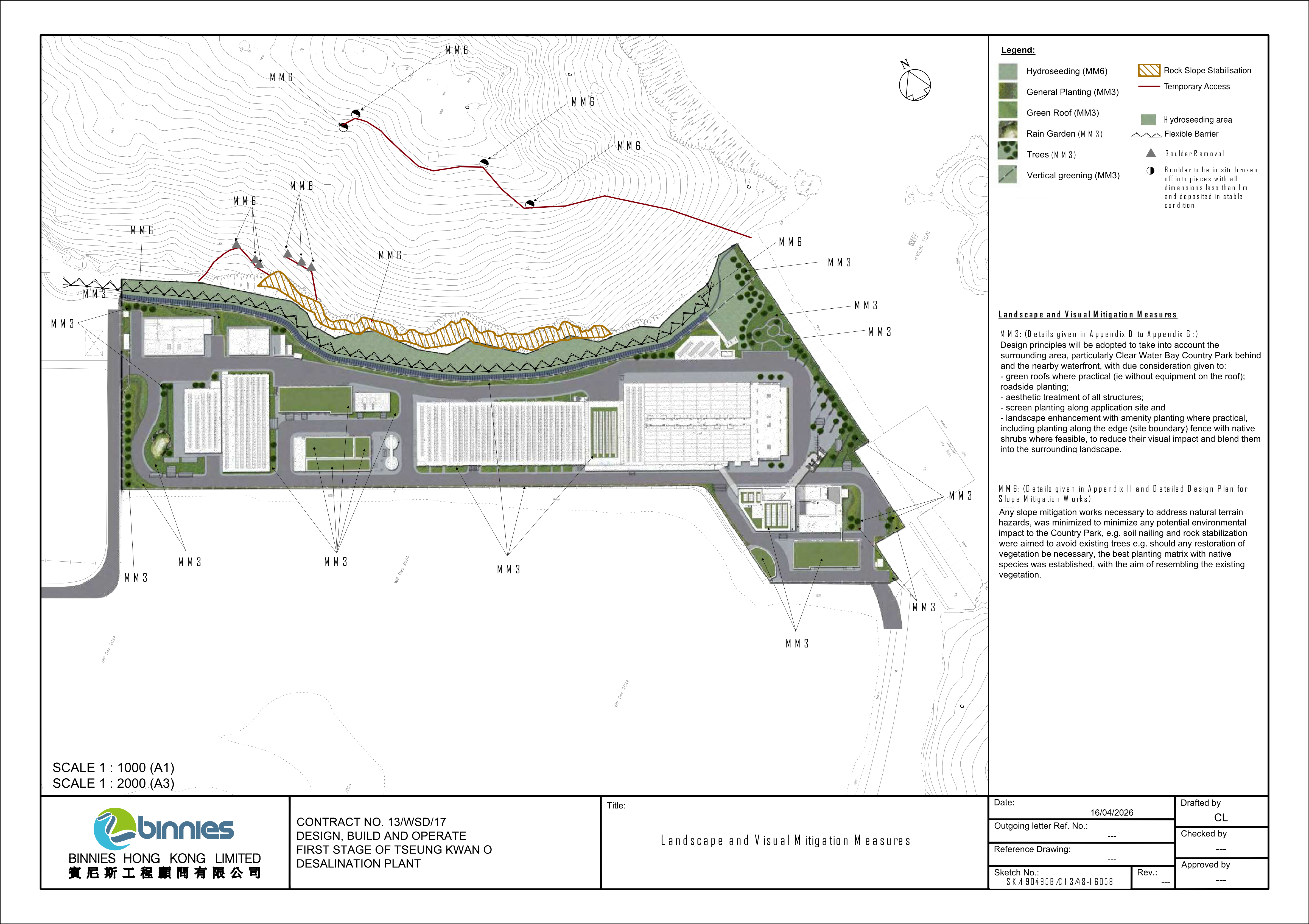


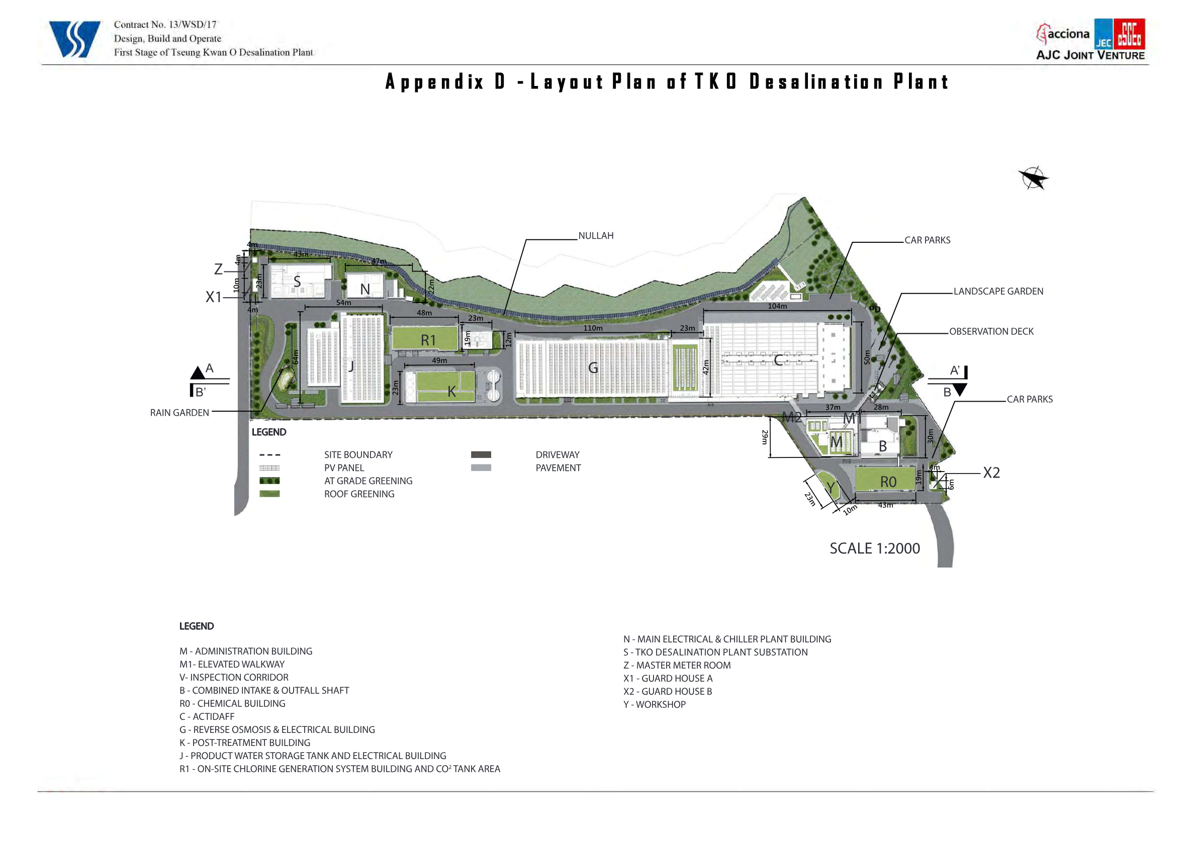
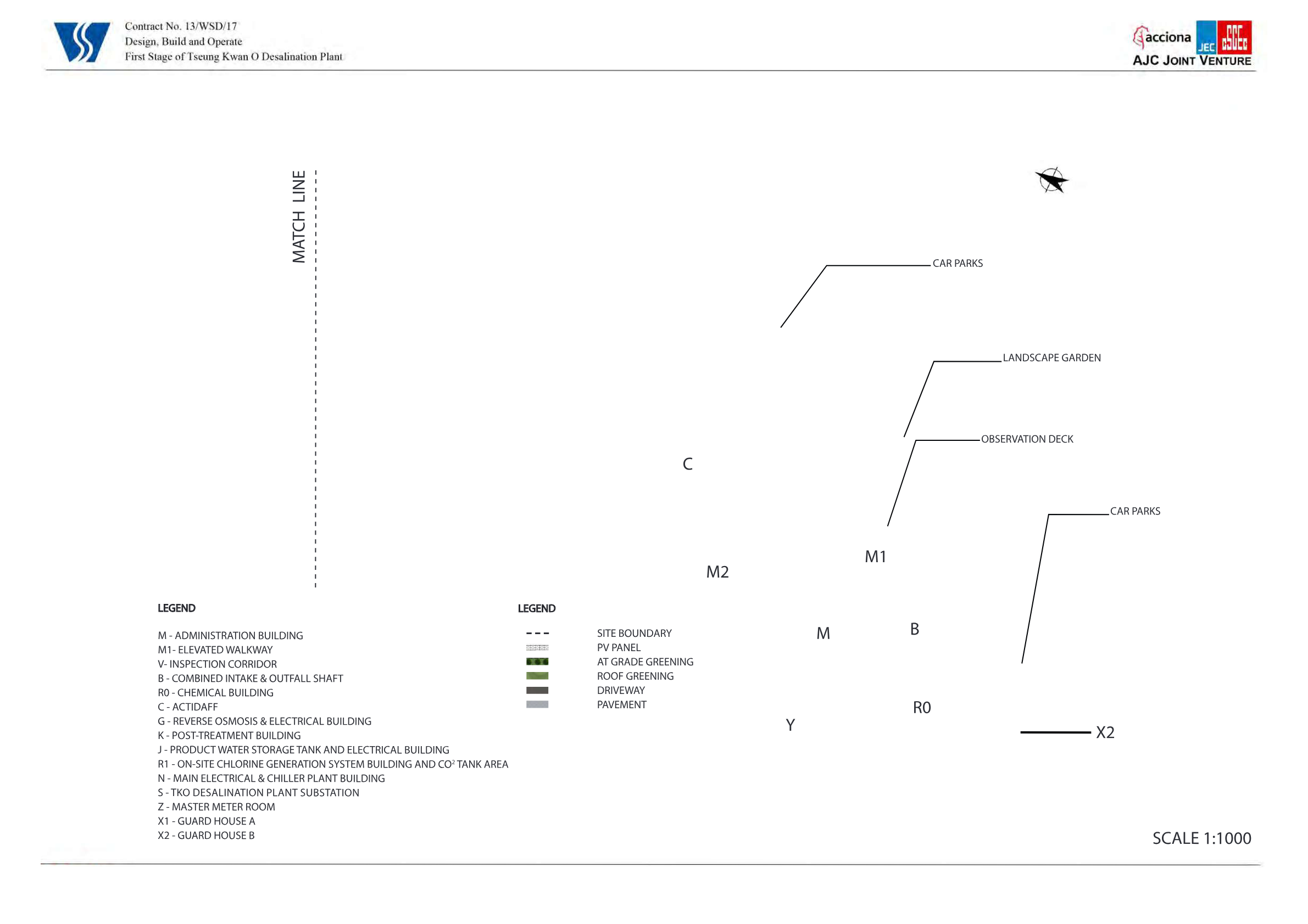
Design, Build and Operate
First Stage ofTseung Kwan O Desalination Plant
(acciona MW
AJC JOINT VENTURE
SITE SECTION AA’
APPENDIX B
475m
*E ■ m
= r
1 I
15m
SITE BOUNDARY
1)
d
l
THLE.
Dees
22m
SITE BOUNDARY
23m
16m
8m
5 • JJ
it
1 HTLRE,
14 i
u
I
i
K - POST TREATMENT BUILDING
C - ACTIDAFF
G - REVERSE OSMOSIS & ELECTRICAL BUILDING
R1 - ON-SITE CHLORINE GENERATION SYSTEM BUILDING AND CO2 TANK AREA J - PRODUCT WATER
STORAGE TANK AND
ELECTRICAL BUILDING
SITE SECTION A-A (SCALE 1:500)
475m
WTO
35m
I
i
i
i
i
'HMHIEIi
al
1 Hi
FAELL. II
th
_t
SITE BOUNDARY
SITE BOUNDARY
24m
16m
Sillii
15m
10m
7m
10m
i
i
G - REVERSE OSMOSIS & ELECTRICAL BUILDING
V- INSPECTION CORRIDOR
J - PRODUCT WATER STORAGE TANK
AND ELECTRICAL BUILDING
M - ADMINISTRATION BUILDING
K - POST TREATMENT BUILDING
B - COMBINED INTAKE & OUTFALL SHAFT
R0 - CHEMICAL BUILDING
X2 - GUARD HOUSE B
SITE SECTION B-B (SCALE 1:500)
V>|)
Appendix B - Figure B4

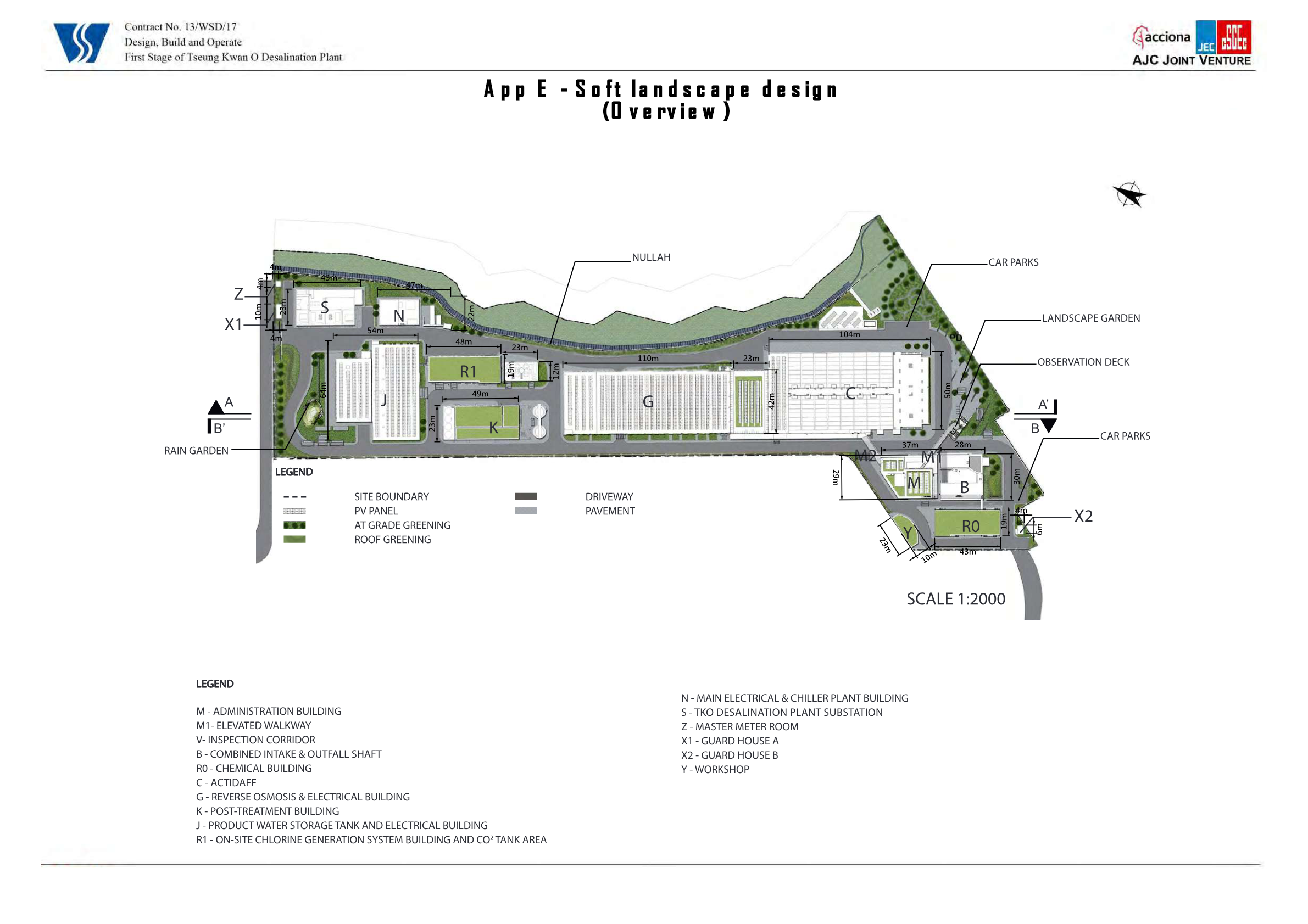
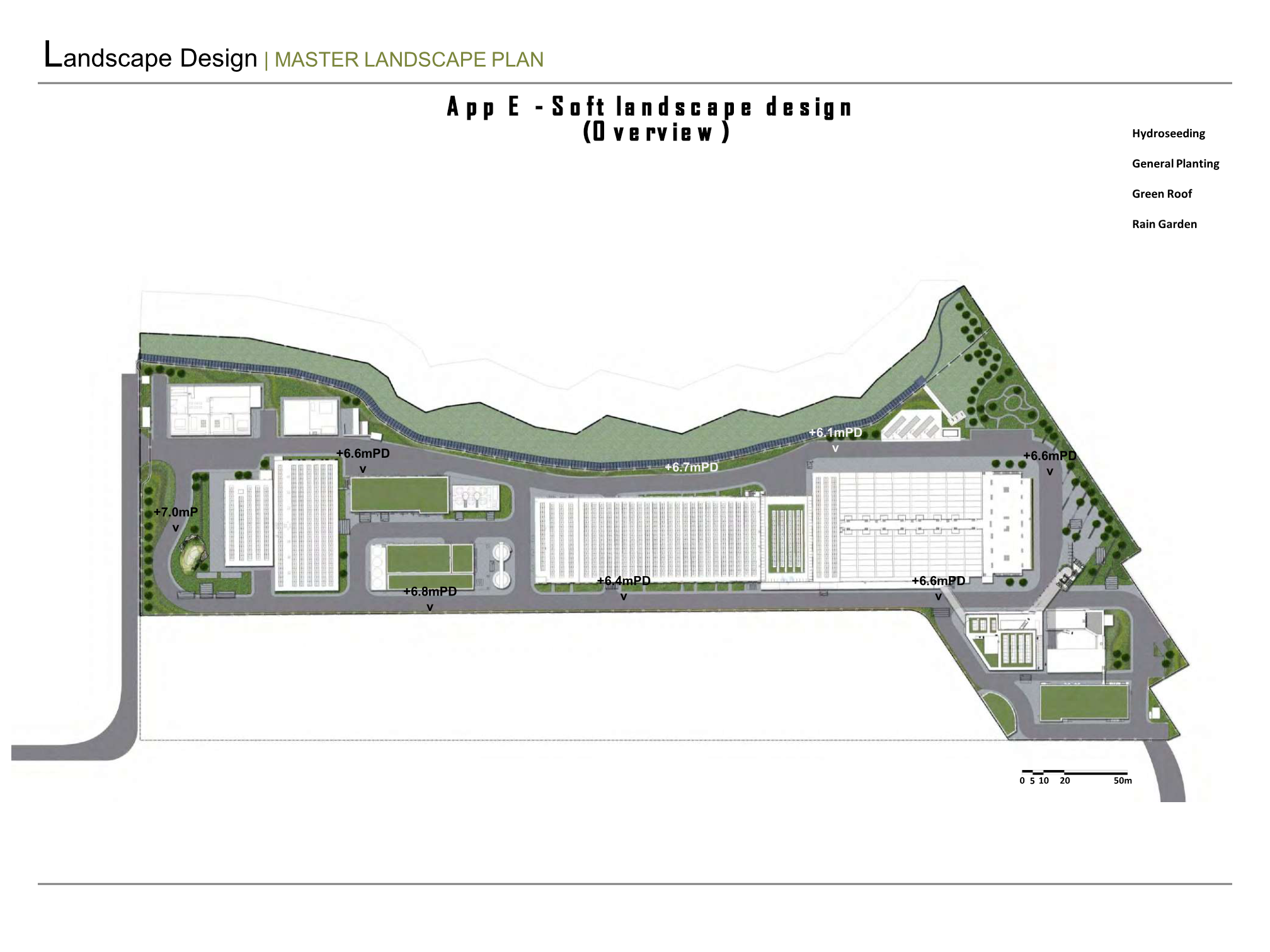
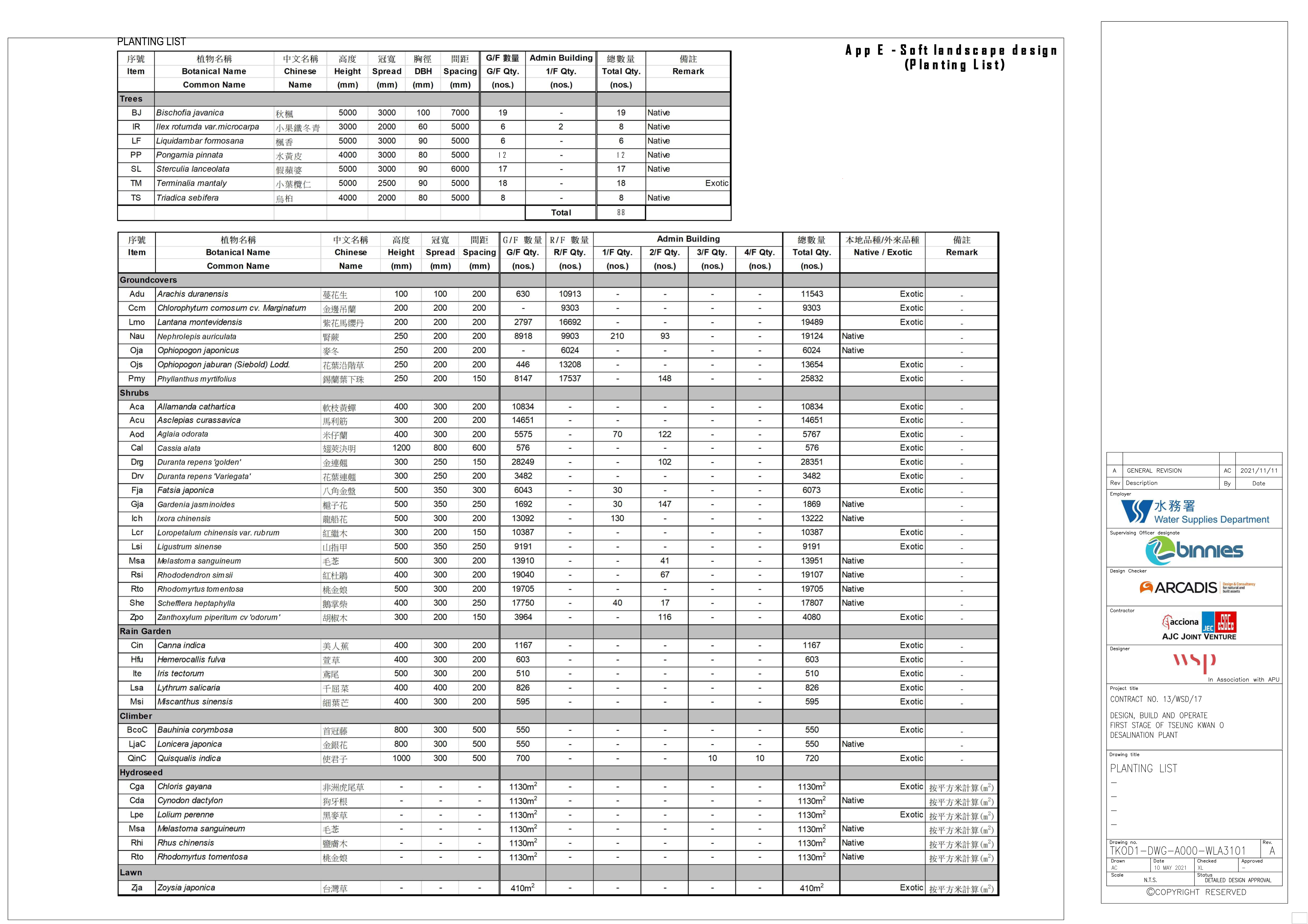
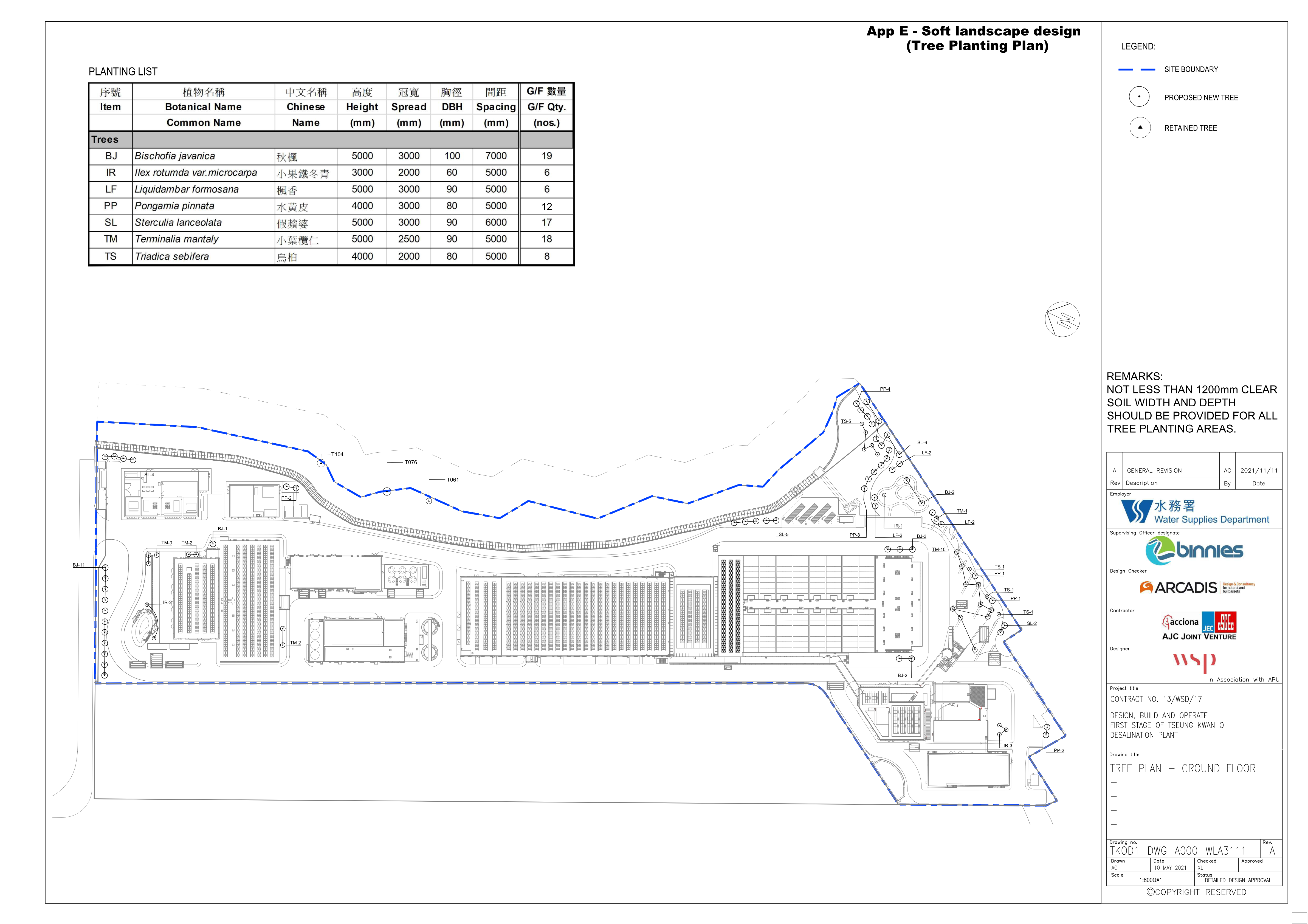
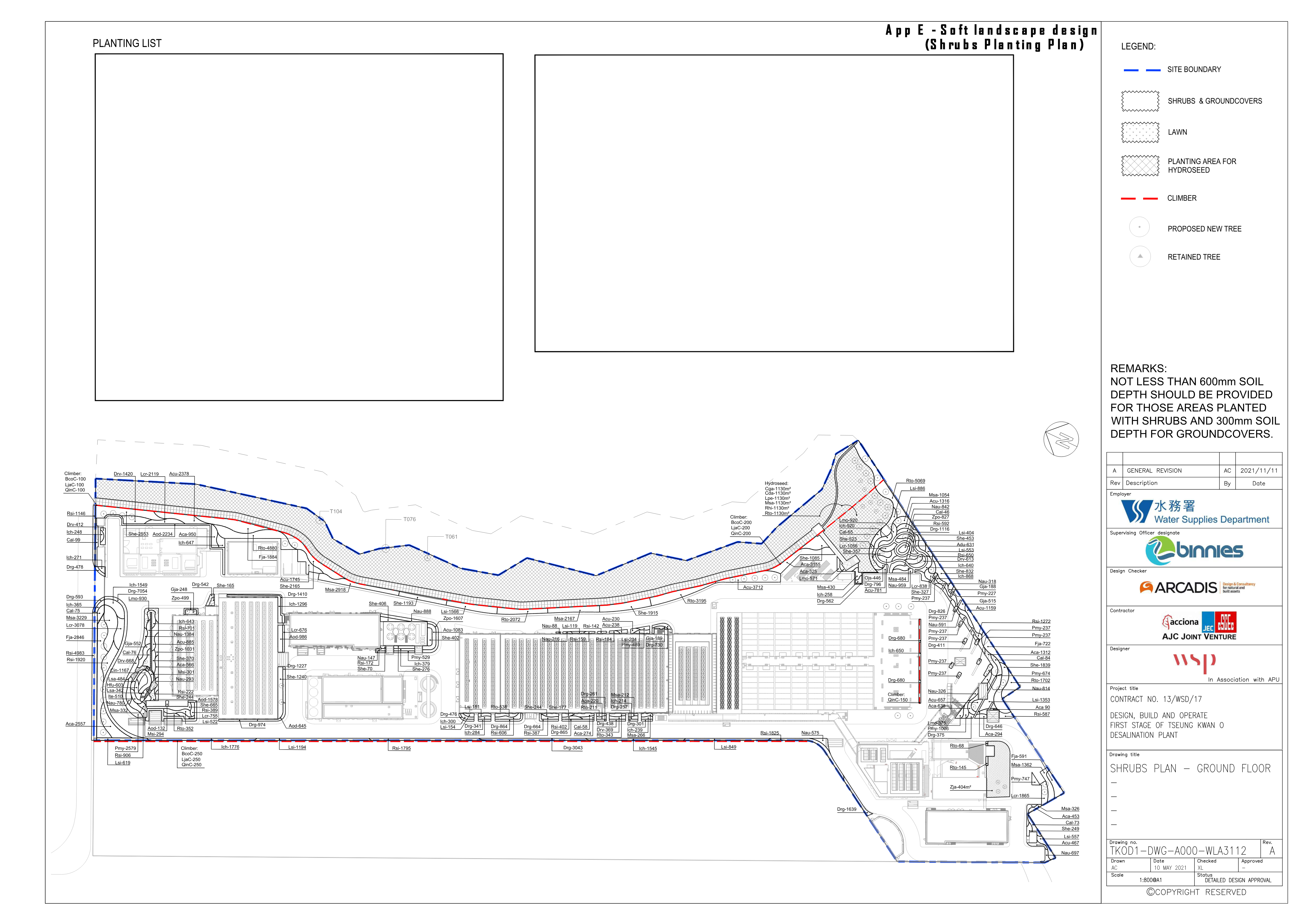
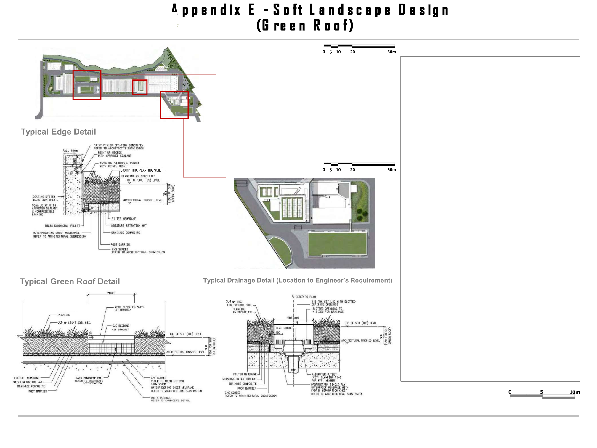
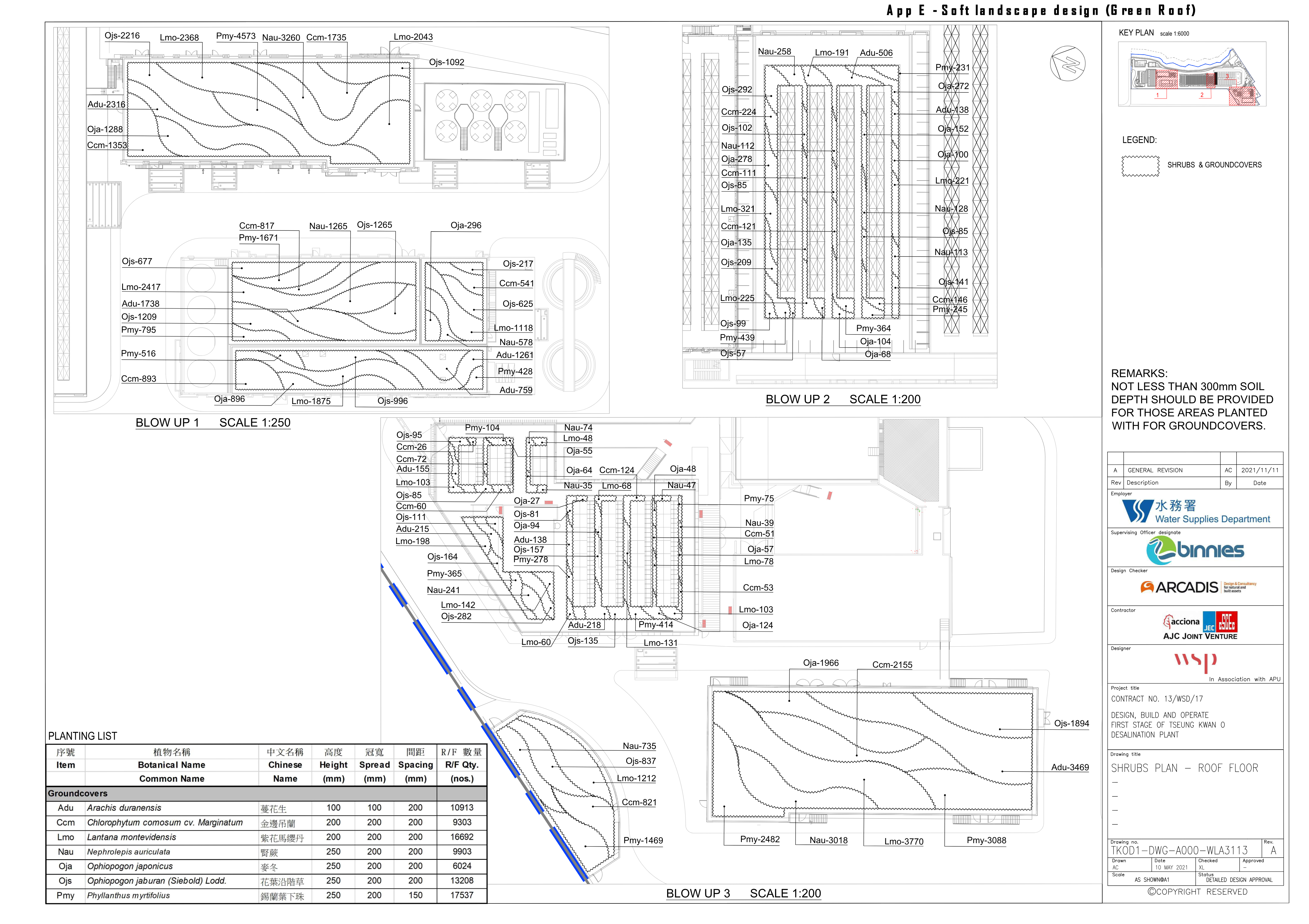
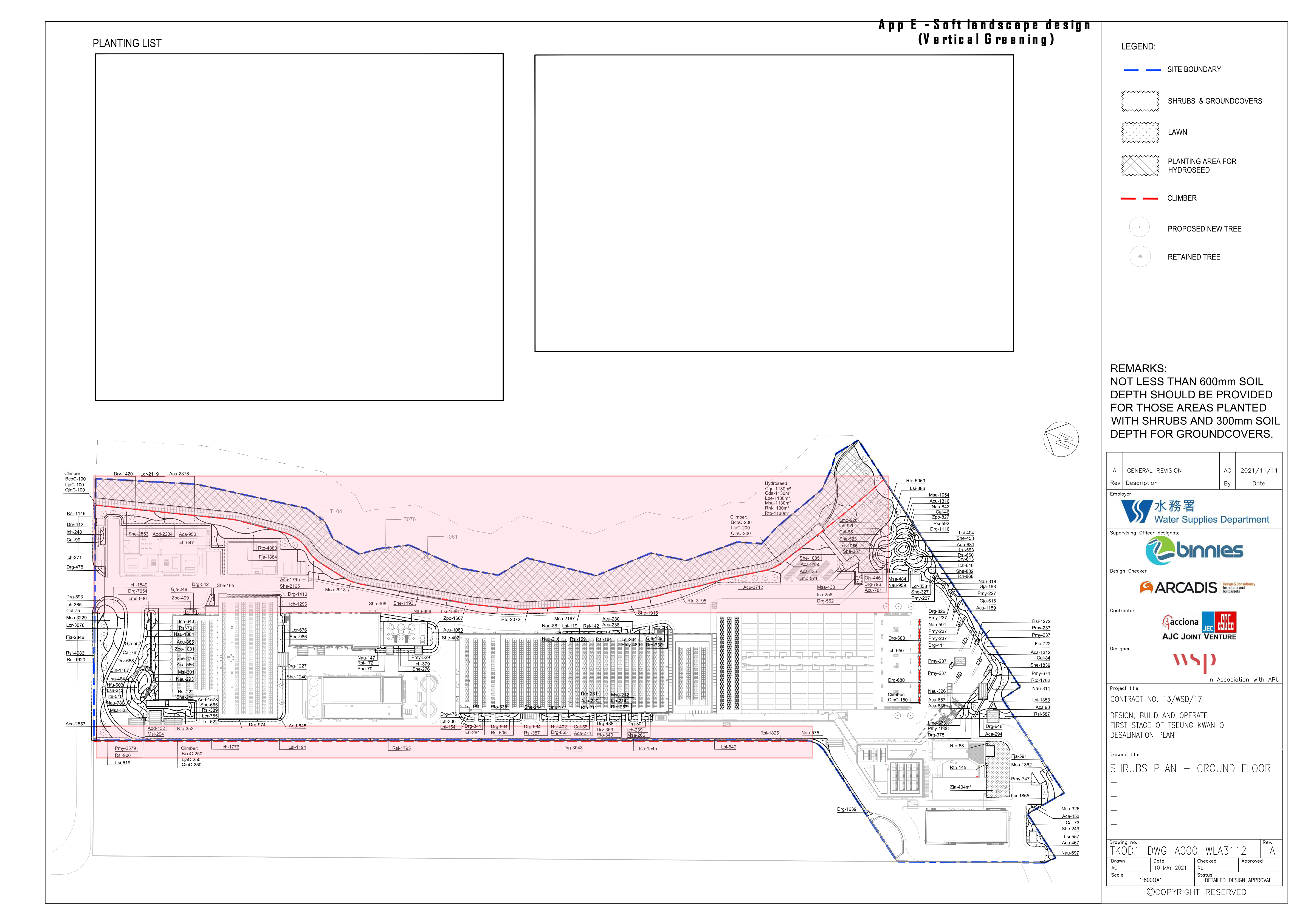
Appendix E - Soft Landscape Design
Landscape Design | Vertical Greening 1
(Vertical Greening)
Typical Vertical Greenina Elevation
- '
,2 A]
1 H
-
il
470 ■w
470 470 wil
ianri rurs
5 Lh" Ge HS
2PU RR wi£
115 WH 4
AMH fl 7 CA
50 . H . 5 W MS. ARE (.E]
7 • % ne MS FLA IOMTSCE)
4 Ai u 5*. HAES SR
M « S ns PT
AE NT$ wT MBER
kui w.ll
.tt
‘T
-
=
ins 1
E has '□ ». HL"
"uMiLr“I NLCE
E 40 W wilt
fl
—
AFTMDELT Jt!
f
SFTE M[WA VETH
Typical Vertical Greening Section
1L
i
MIN. 1.5m
VERTICAL
GREEN
■ i
INSIDE-Plant Area
OUTSIDE-Hillside
l MQ T MME
FI. PDST SMIOIG
« > » i !
ML ME 1
। ma PiFs A
ull RATE Mi NTS
m
w »5 ne us
RA
E
—A
(
i
-
V
j J.
3 ROWS OF
RAZOR WIRE
3 Open Channel
HIGH STRENGTH SECURITY FENCE
6 x 25 COVER STRIP
Vertical Greening adjacent to Open Channel
100 BOLTS S NUTS
Proposed 4m high 5000kJ flexible barrier HIGH STRENGTH SECURITY FENCE
Post
MIN. 1.5m
VERTICAL
GREEN
Ringnef .
Upslope cable
3.550 GMS LINE WIRE
3 v
50 x 50 X 6 L
INTERMEDIATE
L
Proposed Ground Level
0ST AT 1825 Ct
f
3.5m Min.
V
Flexible Barrier
3 Footing
within Part Area
Open
Channel
with min. 2m depth
Proposed Open
a
Channel
base slab
*
M
3 0m
4
upsfope anchor
upslope anchor
Appendix A - Figure A14
TKO Desalination Plant
Appendix E - Soft Landscape Design
Landscape Design | Vertical Greening 2
(Vertical Greening)
Typical Vertical Greening Zoomin Plan
[
]
INSIDE
IT
3000 1 rrve
ree
■
2900 1 ERTICAL GREENING (REFER TO LANDSCAPE DRAWING)
smr’d
100X100MM G.M.S. POST-PAINTED IN BLUE 8300 C/C s
a
I
50X100MM GMS.-RHS HORIZONTAL RAIL PAINTED IN BLUE r
RAZOR WIRES
-3 LINES DE MS 2-PLY BARBED WIRE 225 WITH 4
POINTS BARBS AT 75 C/C
1 do
150X150MM POWER COATED GMS
SGS FRAMES DARK GREEN COLOUR
4 c •
J u u u u u u u u u ulj u u u u u u u u u u u IH
100X100MM G.M.S.-R.H.S. POST-
PAINTED (RAL 7021\
50X100MM G.M.S.-R.H.S. HORIZ. FRAME-
PAINTED (RAL 7021)
8 (
100X5OMM GMS. POST PAINTED IN 3LUE/GREY (REFER TO DEMARCATIUN ON PLAN)
8
43
|OUTSIDE|
51
yp.) 75(Typ.)
50X100MM G.M.S.-R.H.S.
VERTICAL FRAME-PAINTED
(RAL 7021)
Typical Vertical Greening Elevation
Typical Vertical Greening Section
75(Typ.) 50(Typ.) 75(Typ.)
1171
100109109
n V
/
RAZOR WIRES
3 LINES OF MS.
2-PLY BARBED WIRE
32.5 WITH 4 POINTS
BARBS AT 75 C/C
C
8
RAZOR WIRES
8 t
I
o
O
■
e
%
—2
■
CT
L
.1
—
—
s
As
A.
■
J
g"
8 3 2 _ _ —
in
t 7
S
Q
s
is
100MM GM.S.-R.H.S.
HORIZONTAL RAIL
PAINTED IN BLUE
L
2 U
ra
i
is
5”s
2 I
5
—
”
C"
2 2 2 4
h P
■
E
s
- “
%
*
T
-t
a
%
3 4 ■ t
e r
3
50X100MM GMS.-RHS.
HURIZUNTAL RAIL
PAINTED IN Bl. UE
100X100 GMS-
POST-PAINTED IN
GM.S. ANGLE FIXED
WITH BIILTS t NUTS
s
BLUE 2300 C/C
1 s a
*e sp
■ t.
Jt / ;
?
■
i
)
■
2
-VERTICAL GREENING (REFER
TO LANDSCAPE DRAWING)
7 %
■
1 P
5 $
d
y
r.1
d
>
?
C
t
V
.2
i.
>
s
"
-
9. •>
(
5 1 ?
J
d
! -
'J -
2 3 r ) v
-
100X100MM G.M.S.
POST-PAINTED IN BLUE
■
2300 C/C
t
y
Q
in
t
&
o
CT
in ()
100X50MM GMS. POST-PAINTED IN
BLUE/GREY (REFER TO
DEMARCATION ON PLAN)
J
4-'
s
7 s
100X50MM GMS.
POST-PAINTED IN
BLUE/GREY (REFER TD
DEMARCATION DN PLAN)
■
C
? k 1
— e
• $
4 e
i
7
1 CT
in
Y
w
P
5 -
i; r;
r
GJ
£
f
s
i.
4 V *
‘t
2 /
t .
I OUT SI DE |
| INSIDE |
> <
is
s '
5 A £
B
)
< /
"
9 — s -
I
■ e
k s
pi $A s
y
N
t
A
/ ,
C
3 N
I59 V,
7 M
%
4 f
V 2
s
i • ■■
- -
■
f
-FILLET WELDING
/
4 i
( P
st
3,3
2 2 2 ■■
s s
F
I
I.S. BASE PLATE
r
2 5 3 _ f
L __
o—
50X100MM G.M.S.-R.H.S.
HORIZONTAL RAIL
PAINTED IN BLUE
, s
22 •
. -ANTER REFER TO
LANDSCAPE DESIGN DWG
, en x
- ■
te
T —
f
> h
.$
3 1 ERB
-
V
‘E-
OY
4 — t
y
5 J
for
77 ■ 3 ■"
-
1
C &
5 A -
o&
.2 >-
w
' sk
CARRIAGEWAY
J
1
rJ
s.
3000
CA
CONCRETE FOOTING
(SIZE REFER TO
STRUCTURAL DRAWING)
—4
Appendix A - Figure A15
TKO Desalination Plant
Appendix E - Soft Landscape Design
(Vertical Greening)
Landscape Design | Vertical Greening 2
... a
AU
ini
I
M
Typical Vertical Greening Section
Typical Vertical Greening Elevation
100090%
75(Typ.)50(Typ.)75(Typ.)
1111
r
r
1 RAZOR WIRES
3 LINES OF MS.
2-PLY BARBED WIRE
22.5 WITH 4 POINTS
BARBS AT 75 C/C
o CU
RAZOR WIRES
( in
I
M
3I?H
H
8l212
II-
C
o
o
o
5
s
I
3
33
-t
. 7
4 -
7
7’
1 S,
Ml Lu
—A
*
1
V
a
th
*1
E c
2 1 $ ■'
S0X100MM GM.S.-R.H.S.
CT n
HURIZUNTAL RAIL
PAINTED IN BLUE
7 s
t
A7 A y
o.
■
=
a
—
—
T
T
p
/ -
W
3 I3
2 < !
*
1 ■
A
z
*
1 4
1 %
li
%
1 /
-
• *
.4
7 M : N
M
7 11 7 !
y
5 5 J
J
J
. ■
a
2 7 7 s
"$
4 -t
I C
: u
2 § s
50X100MM GM.S.-RH.S.
HORIZONTAL RAIL
PAINTED IN BLUE
1
3
GM.S. ANGLE FIXED
WITH BOLTS 4 HUTS
E
r
a
T
S
wh
£b
2 i
s
ft
A
21
■
7
100X100 GMSr
POST PAINTED IN
- ce
l. I 2
s H 2
BLUE 2300 C/C
e
; I y
--°4
$
-VERTICAL GREENING (REFER
■
=
"u
TO LANDSCAPE DRAWING)
C s
3
7
‘4
< -
1
P.
4
A-
7 :
100X100MM GMS.
POST-PAINTED IN BLUE
5 . 2
■,
*
1. s -
• 4
1 j
7 t’t
/ J
J u
4 <
- <
%
J
j
• ]
2
0 2300 C/C
-
■ ( s
1:
i s s
cuf “e. -am
O
o u)
()
4,’
hij
-
_ —
H t
′ -
Q
CT
in()
j
100X50MM GMS.
POST-PAINTED IN
■
677
1.
2
■
r I
.4 ,
2 "
- a J . 4
-
57a
* I
"J
'J
4
-3
1
£ -
i -■
2
Cu
*
100X50MM G.M.S. POST-PAINTED IN
BLLE/GREY (REFER TO
DEMARCATION ON PLAN)
BLUE/GREY (REFER TO
DEMARCATION ON PLAN)
CT
m
1 ...
1 -
%
$
I
* I
r1
e »
st
-
,3
k
i rlJ2 -
OUTSIDE
INSIDE
6 e
■ 1
J
1 f
%
-
7 4 3 22 24 2 *
> f
s wi
j
A
1 2 ;
' I
] —
. L
’ * I
4 ■
— 1
-
-
A
»,
ILLET WELDING
J $
r
1A
2 t - - '
“ 2
va
13 ■f.
j
—
3 w
GM.S. BASE PLATE
al
FT
d
' 1
—
p
s
H
Fs
2
i
y
te
-
s
1.1’
■
4 i C
e a
s
?
j
I
r
5
3 }
>
c
K
w
2 h
2J
>■(•
Le
’1
-
. ?
BI
N
f
I
lb
E1A
1 - t
Ie
/I
' r
hr.4
ST
I
P
3
50XI00MM GM.S.-R.H.S.
HORIZONTAL RAIL
PAINTED IN BLUE
■I
- -
2 i
t
4 s
I
Voe S
.
/ 2
—
A —
yee
—
—=-
t 7
o—
r i
o
r r
ERB
$7
i f
37 ..
5 4*
PLANTER REFER TO
LANDSCAPE DESIGN DWG
q r
-
09 —
O
o cu
(he rep
o
f "
- ' 4 “t
-57 .
DC *34 ■ . —te.
—
2 ■
CARRIAGEWAY
J
FE-
o'
> “ - 7
—
J
• —
Y
i
s.
*,‘2 "
24
• =raw) w
4-7-2-ct
47. 6.
{".4‘a
CONCRETE FOOTING
(SIZE REFER TO
STRUCTURAL DRAWING)
Appendix A - Figure A16
14.d.
TKO Desalination Plant
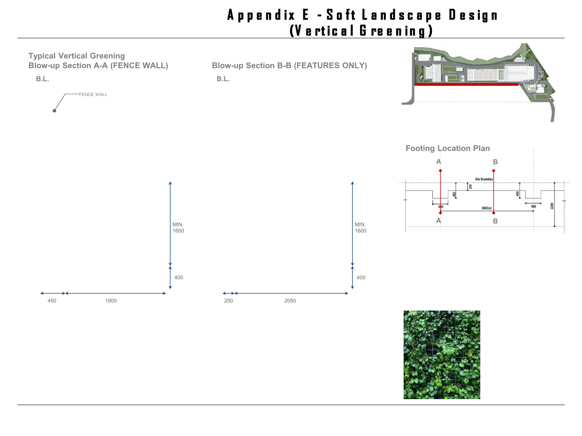
Appendix E - Soft Landscape Design
Landscape Design | Rain Garden
a
IP
s
d
dd
3 g
CONCRETE PAVER
BLOCK
OVERFLOW DRAIN
IK
PEBBLES W/ 15 -
20mm DIA
RAIN GARDEN PLANTING
approx. 152m
approx. 98m
FEATURE ROCKERIES
(NATURAL ROCK)
STONE BENCH
*■
L
1200mm
-
CONCRETE PAVER BLOCK
o
a
PLANTS WITH HIGH
TOLERANCE TO
FUNCTION OF HUMIDITY
(PLANTS REFER TO
PLANTING SCHEDULE)
600mm
"HrH
STONE BENCH
a
MAINTENANCE PATH
SAND DRAINAGE LAYER
GRAVEL TRANSITION AREA
SANDY LOAM
FILTER
MEDIA
- —
saw
■ ■
I
a
I
I
3 S-s
TO THE NEAREST DRAIN —
(SLOTTED DRAINAGE)
PIPES WITH FALL
0 5 10m
Appendix A - Figure A2
TKO Desalination Plant
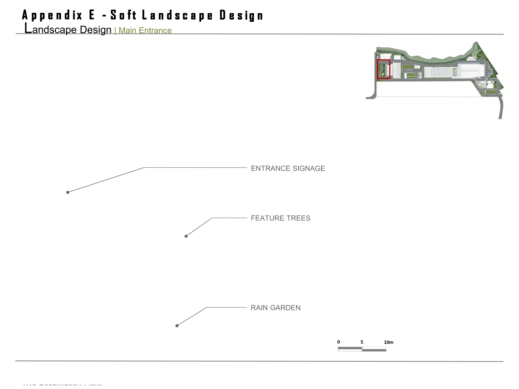
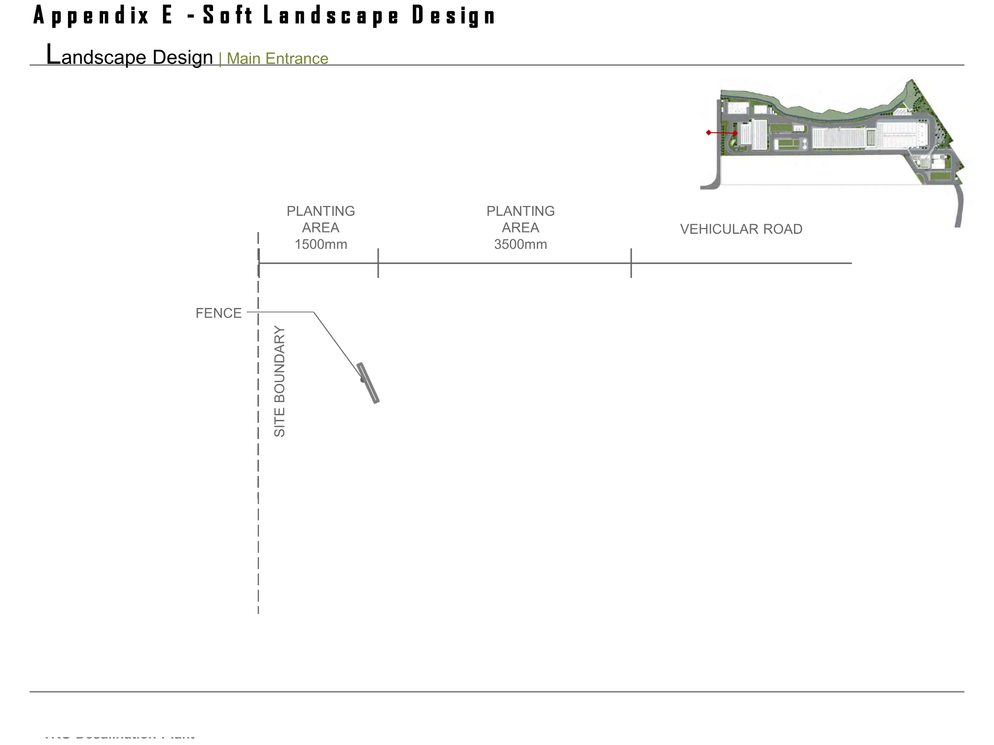
Appendix E - Soft Landscape Design
Landscape Design | Drop off Plaza
0
5
10
20
50m
t
r
s
..
I;
r III
&
BLOW UP AXON
f
PLANTING AREAS
AT-GRADE PLANTER WALL WITH
MIN 1200mm (WITHOUT
DRAINAGE LAYER) SOIL DEPTH
“aree
£
ne
oshe
d
PAVER BLOCK WITH
RANDOM MIXING
FAIR FACE CONC. FEATURE
(800MM WIDTH)
------T
4 e&
::
1
8-
drainage layer)
(without
in
co ----
o
Vi
M-------
PLANTER BOX FAIR FACE
CONC. FEATURE
(1500MM WIDTH)
V
I
2 \
Y
"L
i
-A SECTION AT-GRADE PLANTER WALL 1 I al' MANHOLE WITH MATCHING FAIR FACE CONC. I COVER FEATURE r — — GRANOLITHIC FINISH PLANTING 1 PYO PLANTER ALONG STAIR AREAS IT II VA 11 Ltae 0. 11/ \T ! LL..X A - . $ “Wwav • IW‘33 I |
|||
WALL 1 I CHING FAIR FACE CONC. I FEATURE PLANTI STAIR AREAS Ltae - . $ “Wwav • IW‘33 I |
|||
PLANTI |
NG |
||
AREAS |
! |
AT |
- |
GRADE PLANTER |
WALL |
&
—
—
r
22 1
F
Appendix A - Figure A3
TKO Desalination Plant
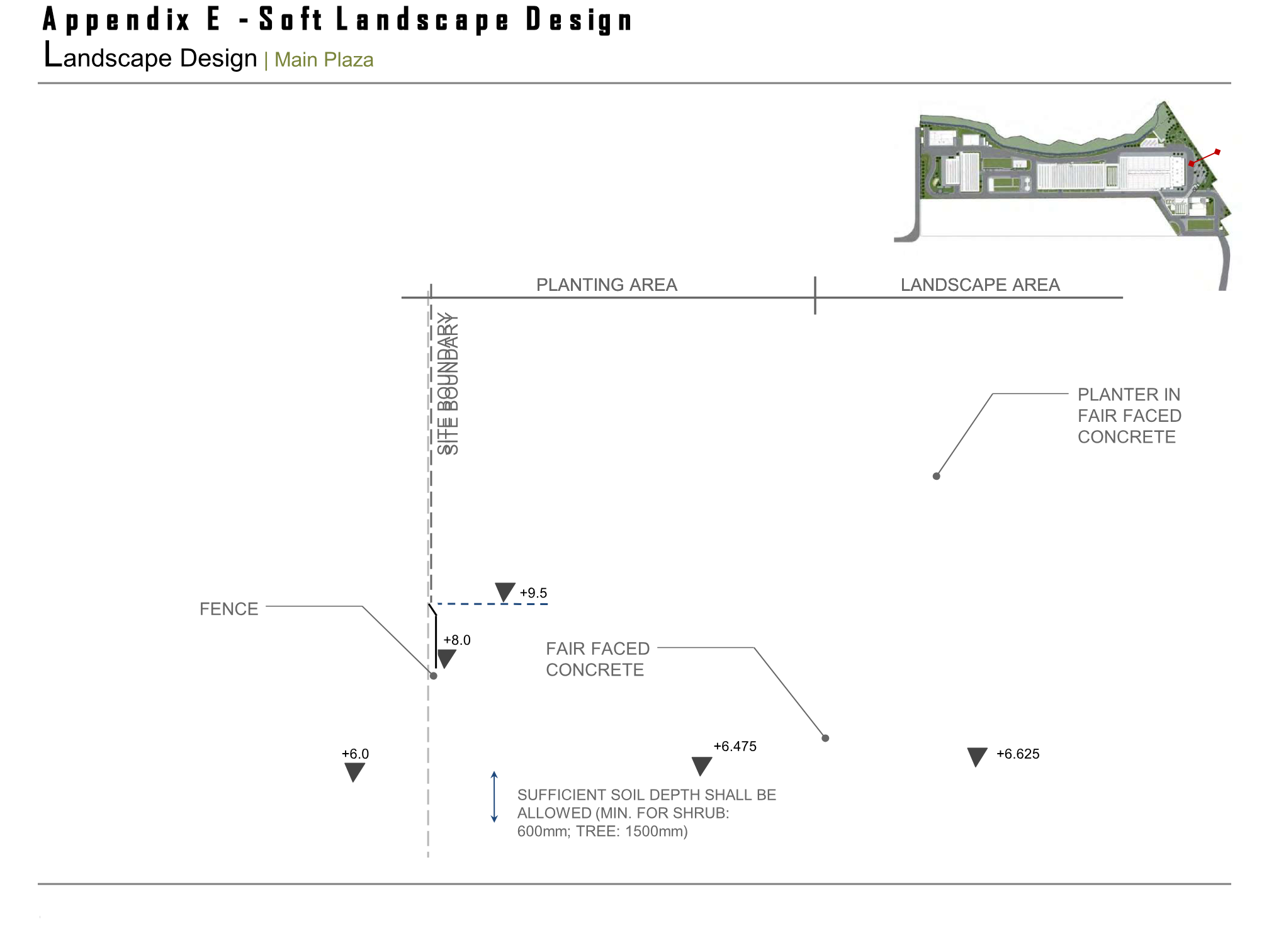
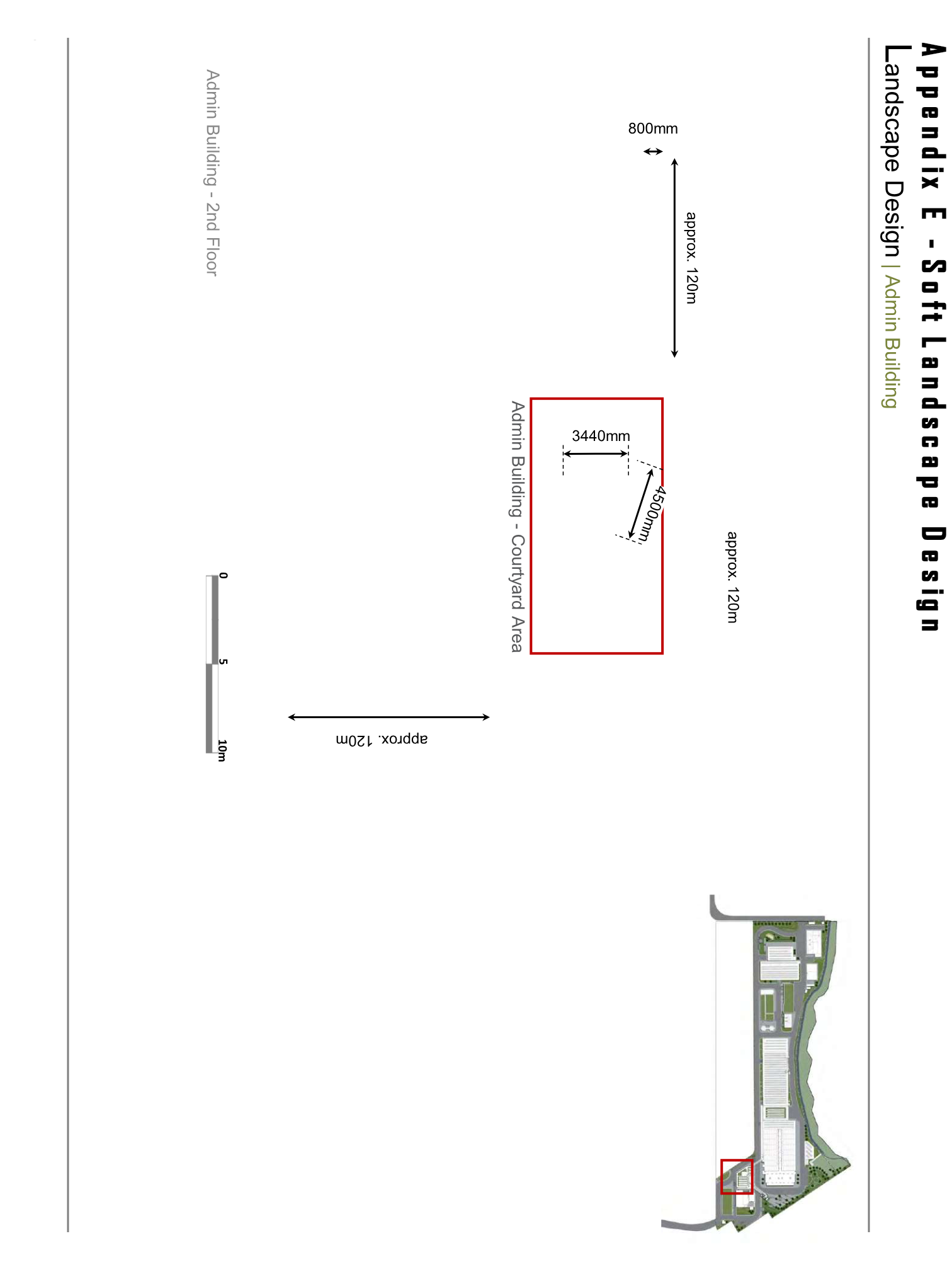
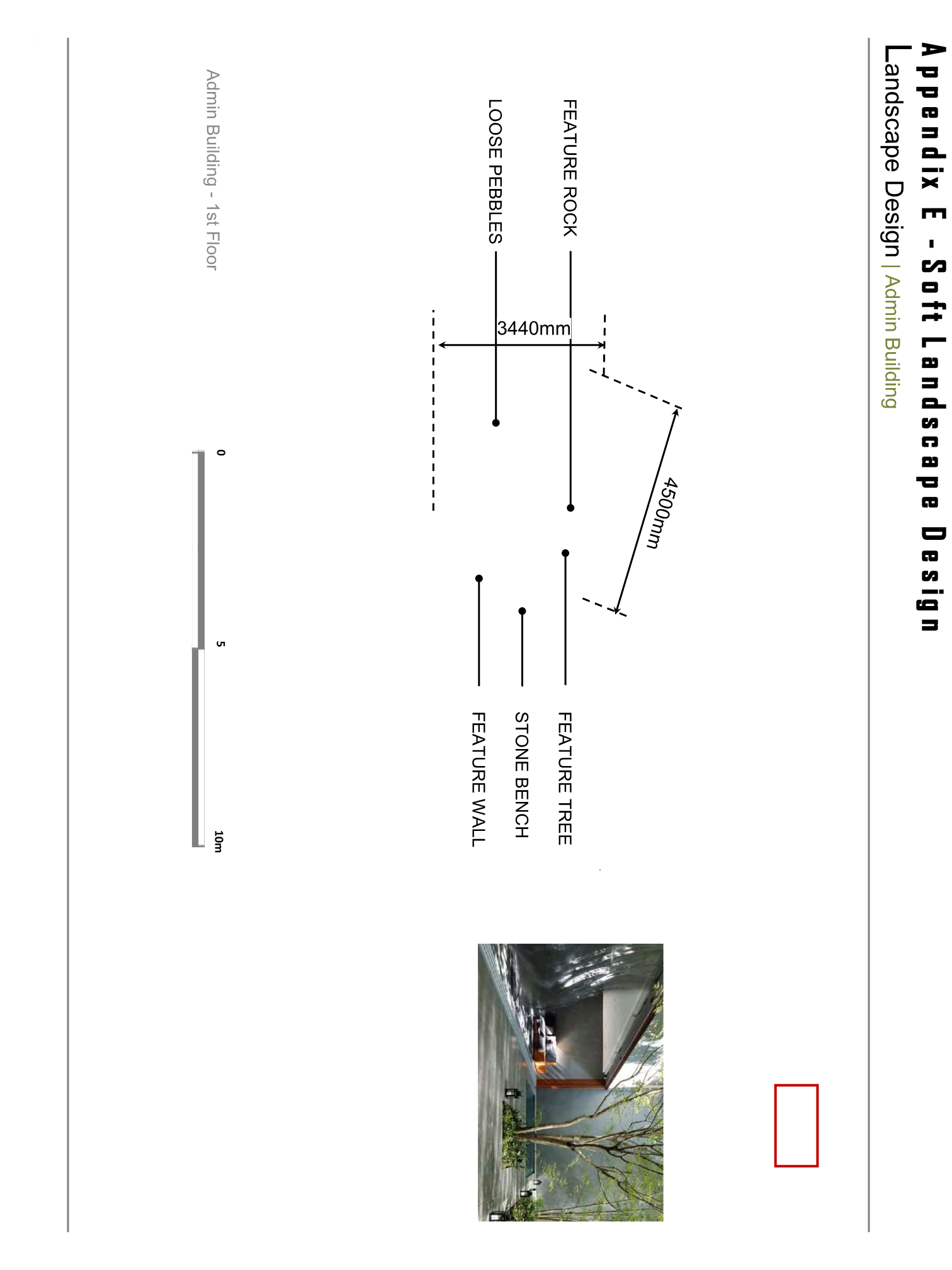
Appendix E - Soft Landscape Design
Landscape Design | Admin Building
I
I
l -
5. 1— -
—
i
i
I
i
I
r
i
i
i
A
B
: A
—
1 —
44 MAX 30“ SLOPE
MAX 30“ SLOPE
F
FLOOR FINISHES (BY OTHERS)
J
w KY
AAAg)
MlMav
HOMOGENEOUS TILE
300 X 600 X 10MM
(T-14)
1,
« s
“ex
7/ v.
$ )
CAO
FAIR FACED CONCRETE
APPROX
10-20MM
LOOSE WHITE PEBBLES
(P-01)
Ul/l/
29/1
y
A | LD
STONE BENCH 1
500 72/X7
. 1
tr
4
4
A
2
*
8 T
Z
2
CM
2 2
%
T
1 SI
,d
n.
4,
E
4
I
d
4
4 d
4 4 4 /
(
SOIL MIX
d 4 a
— WATERPROOFIN
SOIL MIX
ING
HTTI
3 7 REFER JO ARCHITECTS SPECS
d
4 H
ABASF MASTERSEAL M800 WP02)
d
d
d
WATERPROOFING
REFER TO ARCHITECT’S SPECS
REFER TO
DRAINAGE DRAWINGS
Section A
Section B
Appendix A - Figure A7
TKO Desalination Plant
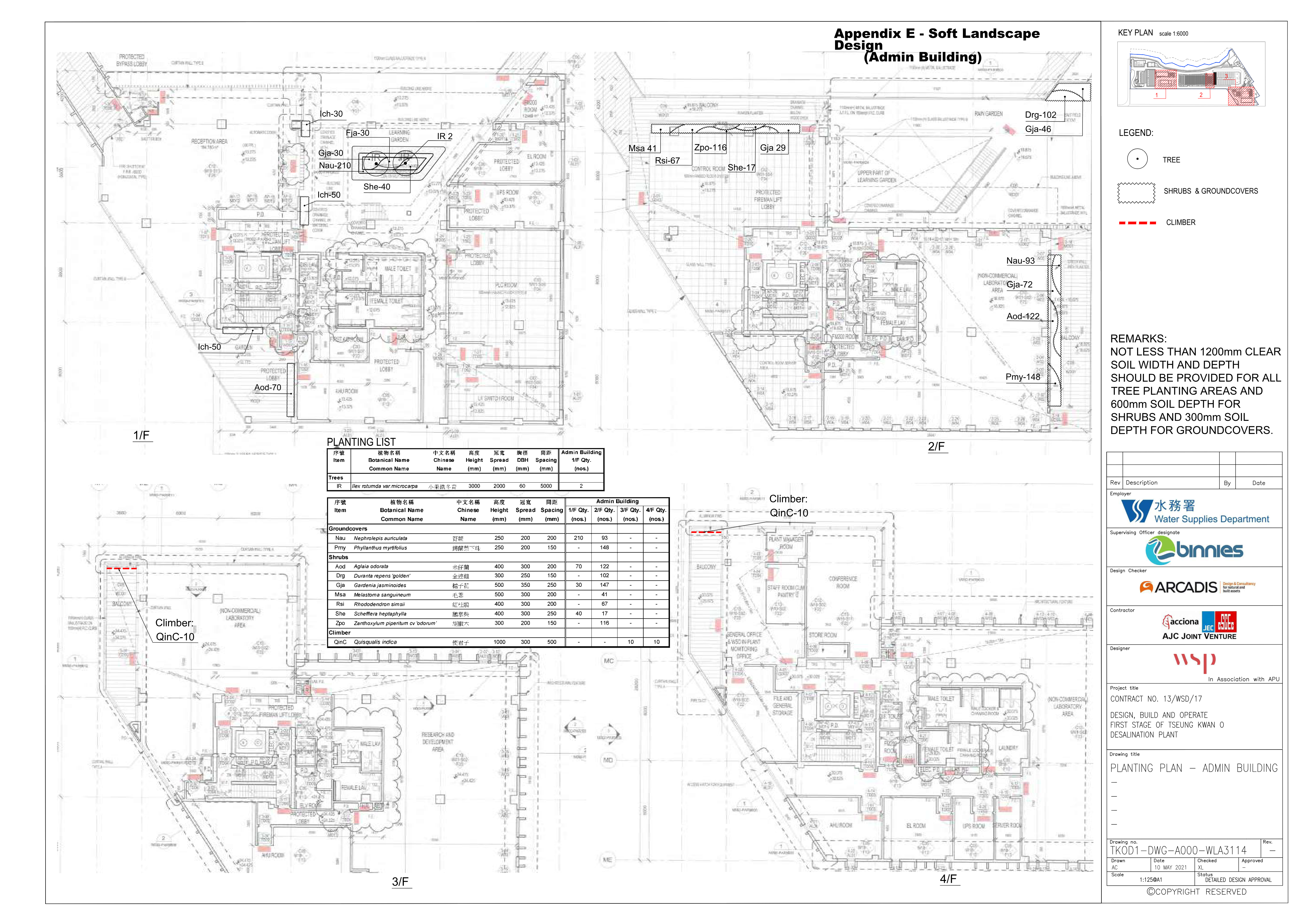
Appendix E - Soft Landscape Design
Landscape Design | Green Area Calculation
SE 5CUNDAR:
P
\\
I I " ■
I
VERTICAL GREEN 2
I
/
t
eNAABar
shssserssnssteraane
a
)
• 1
t
\
ur
1 19
2 ⑤
⑪
keele
ott
0
=•
—
Y
*M
"Ye
X ‘
⑮
FENCE
\
■ I
y
K
——-----
3 — -
I
LANDSCAPE PLAZA
③
⑥
Ⓐ
⑩
⑫
.
■ dee- 4
--
- — ----- - --
—— •-- I
- lew = =L ( “
l7
I
?
'ft
⑦
l | 1
“•—•
*
RAN GARDEN --
y g
if
1 a
/
—
!
r 5
- t
1’07
②
Ⓒ
■
r
Ⓑ
l
-13
I
f
-
.-----
o
④
5 _ I -
(2 -
N
I
-
")
TT
/
—
⑧
⑨
①
saunanussouonssnaann»sanT
oNNNEcinunnuzaak
Hl—A
ASSESSMENT AREA -AE
Ⓓ
VERTICAL GREEN
L
— —
GREEK ROUF
BOUNDARY IN.
⑬
' AT GRADE PLANTING
⑭
E
PV PANEL
*•
Ⓕ
SECURITY FENC
/
------- FE :
v
/
—y
ve
Ⓔ
ITEM |
AREA (m2) |
① |
1252.578 |
② |
736.357 |
③ |
42.288 |
④ |
250.301 |
⑤ |
805.819 |
⑥ |
1101.13 |
⑦ |
196.241 |
⑧ |
109.888 |
ITEM |
AREA (m2) |
⑨ |
200.463 |
⑩ |
91.075 |
⑪ |
2245.921 |
⑫ |
663.355 |
⑬ |
318.392 |
⑭ |
259.803 |
⑮ |
5426.849 |
TOTAL |
13700.46 |
ITEM |
AREA (m2) |
Ⓐ |
696.932 |
Ⓑ |
736.342 |
Ⓒ |
197.214 |
Ⓓ |
162.64 |
Ⓔ |
152.508 |
Ⓕ |
622.136 |
TOTAL |
2,567.772 |
0 5 10
20 50m
Appendix A - Figure A24
TKO Desalination Plant
Appendix E - Soft Landscape Design
Landscape Design | Green Area Calculation
SuE BDUNDARY
P
ASS
SYET AR A
—VERTICAL GREEN 2
7 F□
7777717 ⑤
⑪
•)
I
g
wipe LT
ur
-
"•]
tit
U
/
••• ■
1
⑮
FENCE -
dsoiussteitit"
③
I
y (
--
r
l
:•
.-------- LANDSCAPE PLAZA
&l 1
a G
.m.
4=a.
i
stal
...
FAIN GARDEN
=--=—rul
B
" rr t
t
t"s
1"
r
n
⑥
Ⓐ
⑩
⑫
? /
MS
⑦
1 ②
I
Ⓒ
1 I
I
/
Ⓑ
1 ④
I
] J
) B
X
*
- '■!
⑧
⑨
①
MMHHF
UMinnm
IHNUM vassi mi»w
EEL 2l
SICA- GREEN
ASSESSMENT AEA -AL
Ⓓ
. — • BOUNDARY LN
⑬
-------■ AT GRAF PLANTING AREA
>
1 i
⑭
i—-- GREEN R0C5
— -
aa Py PANE'
Ⓕ
Ⓕ
SECURTY FENCS
d
| +
____ FELC
Ⓔ
/
;■S
X.
SITE BOUNDARY: 56,120.8 SQM
30% GREENERY REQUIREMENT: 16,836.2 SQM
15% AT GRADE REQUIREMENT: 8,418.12 SQM
MAX. 30% CAP OF ALL GREENERY (VERTICAL GREEN, GRASS PAVER, COVERED PLANTING AREA): 5,050.86 SQM
0 5 10
20 50m
(Hence, the at grade greenery calculation requirement is achieved) AT GRADE TOTAL PLANTING AREA (EXCLUDING VERTICAL GREENING) : 13.700,46 SOM [1+2+3+4+5+6+7+8+9+10+11+12+13+14+15]
GREEN ROOF (EXCLUDING VERTICAL GREENING) : 2,567.772 SQM
[A+B+C+D+E+F]
(Detail refer to A15 and A16)
VERTICAL GREEN 1: 585.137(L) X 3(H) = 1,755.411 SOM envsanesnenes
(Detail refer to A14)
VERTICAL GREEN 2: 222.689(L) X 1.5(H) = 334.034 SQM TOTAL GREENERY AREA: 13,700.46 + 2,567.772 + 1,755.411 + 334.034 = 18,357.677 SQM (32.71%)
Proposed GAC 32.7% (18358 SQ.M.) > Required GAC 30% (16836 SQ.M.)
Appendix A - Figure A25
TKO Desalination Plant
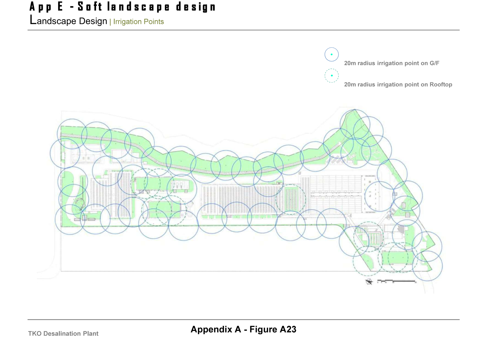


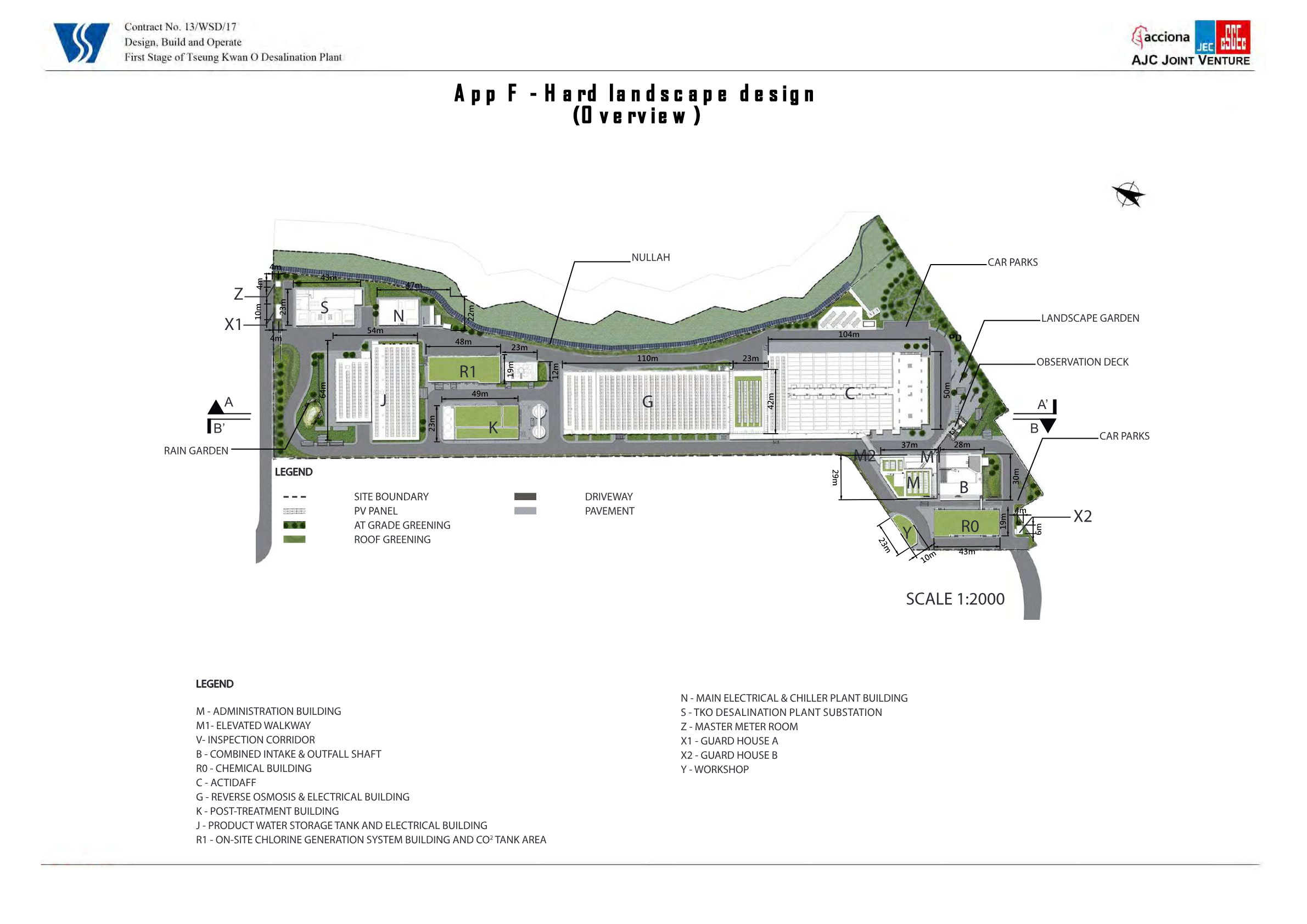
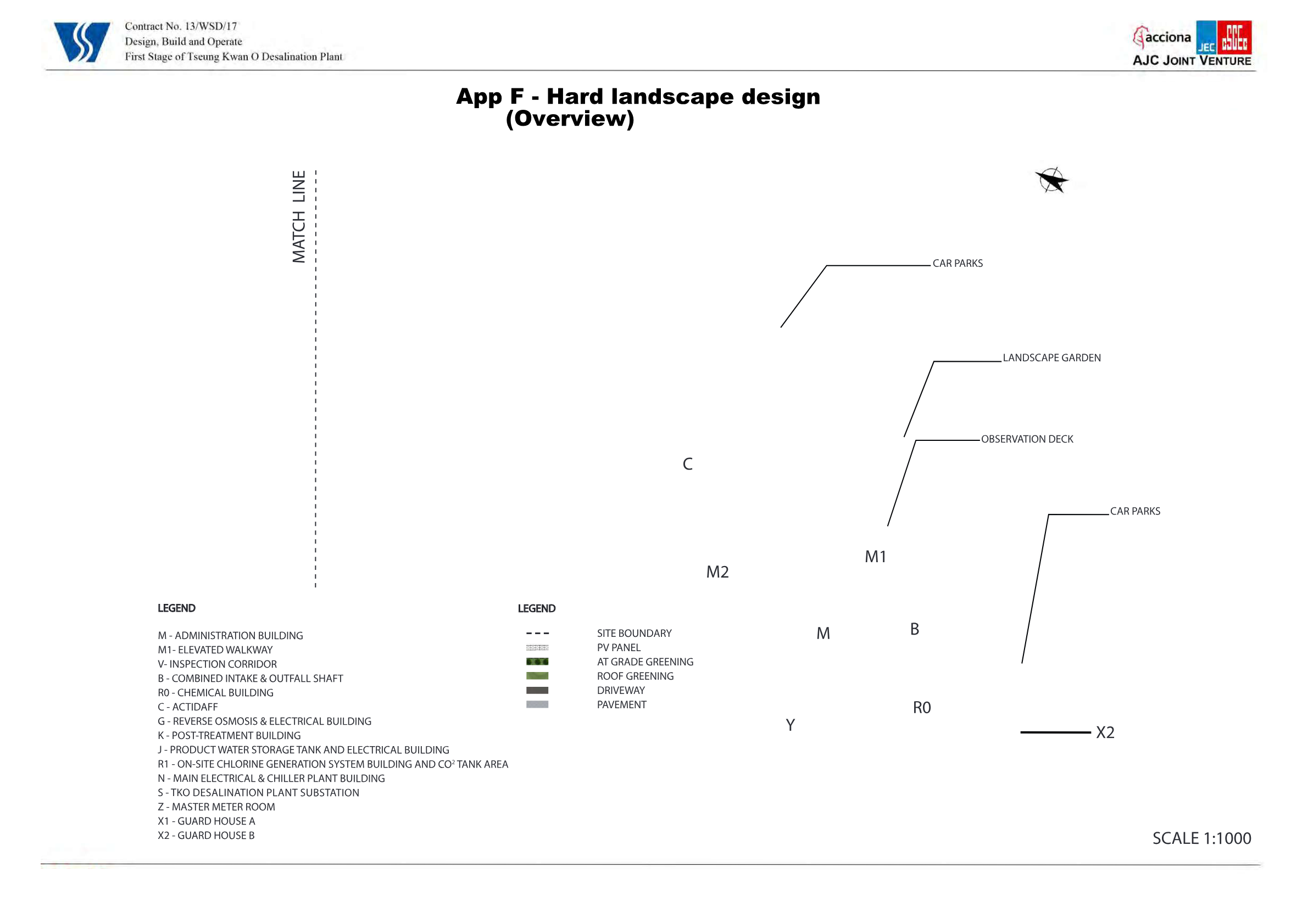
Design, Build and Operate
First Stage of Tseung Kwan O Desalination Plant
(acciona MW
AJC JOINT VENTURE
Appendix F - Hard Landscape Design
APPENDIX B
M - ADMINISTRATION BUILDING
MA
ME
MD
MC
MB
M8
M7
M6
M5
M4
M3
M2
Ml
28200 37200
300
6000
6000
6000
6000
3600
8000
8000
8000
4200
60oo
exe
T
J
n
A
-
11 ““9
I
/
FC
A3 P2 A3 P2 G1 G1 ---- ------ ane
■
49
r J
11
r
h
“HO
TTIIH
——
IMIIIIIH
-JH—
■
*“0
VERTICAL GREENING
t
G4 ilfiA
_LU _LL
HL f
I I
"“V
r
mi
MM
II
-
=
■
■ -
=
"79
ct
ct
FC
G2 —
■
EX
•LV
7 TA
•ro
YIA
\
FC
A5 ELEVATION 1 (SCALE 1:300)
ELEVATION 2 (SCALE 1:300)
LEGEND
LEGEND
FAIRFACED CONCRETE
ALUMINIUM (BRIGHT COPPER)
ALUMINIUM (BLUE)
ALUMINIUM (W/. WOOD GRAIN PATTERN)
ALUMINIUM (WHITE) ALUMINIUM (GREY) S.S. (BEAD BLASTED)
CURTAIN WALL
GLASS WALL
GLASS BLOCK
GLASS WALL W/. REFLECTIVE COATING
PAINT IN GRAY
TEXTURED PAINT IN GRAY
DFMA CONCRETE PANEL (LIGHT GRAY, PLAIN) DFMA CONCRETE PANEL (LIGHT GRAY, BRUSHED) DFMA CONCRETE PANEL (DARK GRAY, RIBBED) P2
A4 A5 A2 G2
SS
FC
A1 G1
A3 G3
G4 D1 D2 D3 P1 1)
M - 04 - ELEVATION
Appendix B - Figure B8
Design, Build and Operate
First Stage of Tseung Kwan O Desalination Plant
(acciona MW
AJC JOINT VENTURE
Appendix F - Hard Landscape Design
APPENDIX B
M - ADMINISTRATION BUILDING
MA
MC
MD
ME
M1
M2
M3
M4
M5
M6
M7
M8
28200
MB
¥
37200
4200
8000
8000
8000
3600
6000
6000
6000
600o
3600
6000 -s
+
G1 |||| |||
to
¥
lUiVOHilUIffl
“O
II
l.l
Ell
ram
—
jimimmimini
IS ............................... t......... ii ........ .................. i G1 P2 1 *WO
—
A3 i
/
I
I
II
T
■
—-
-
I
2 " r
FC
FC
I "Th
Me I
L3 i
/
•■4
j
I
vro
—
m
I
— •
am
::
II
I
—
Si
v n /
—
II
ELEVATION 3 (SCALE 1:300)
ELEVATION 4 (SCALE 1:300)
LEGEND
LEGEND
FAIRFACED CONCRETE
ALUMINIUM (BRIGHT COPPER)
ALUMINIUM (BLUE)
ALUMINIUM (W/. WOOD GRAIN PATTERN)
ALUMINIUM (WHITE) ALUMINIUM (GREY) S.S. (BEAD BLASTED)
CURTAIN WALL
GLASS WALL
GLASS BLOCK
GLASS WALL W/. REFLECTIVE COATING
PAINT IN GRAY
TEXTURED PAINT IN GRAY
DFMA CONCRETE PANEL (LIGHT GRAY, PLAIN) DFMA CONCRETE PANEL (LIGHT GRAY, BRUSHED) DFMA CONCRETE PANEL (DARK GRAY, RIBBED) P2
A4 A5 A2 G2
SS
FC
A1 G1
A3 G3
G4 D1 D2 D3 P1 1)
M-05 - ELEVATION
Appendix B - Figure B9
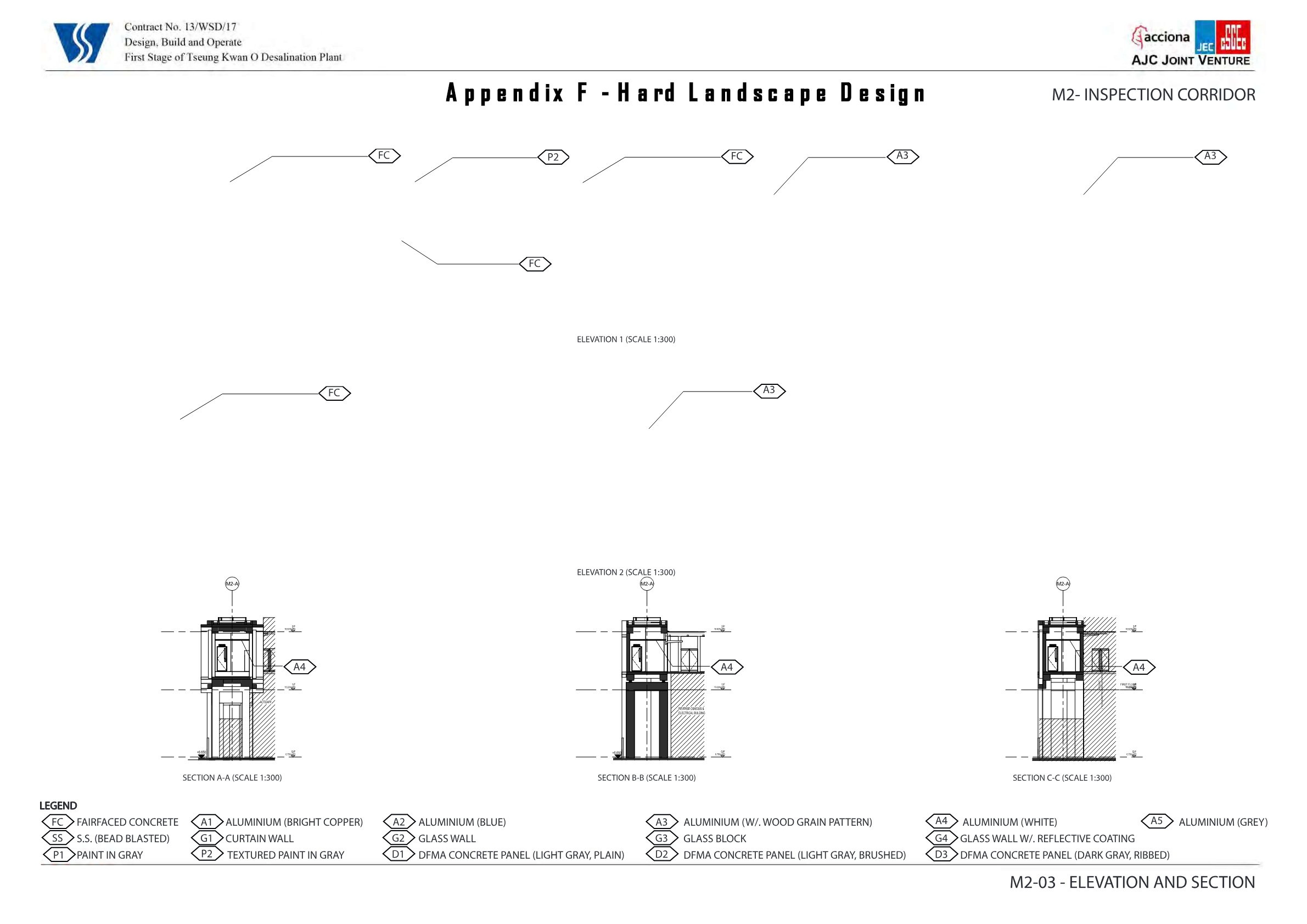
Design, Build and Operate
First Stage ofTseung Kwan O Desalination Plant
(acciona MW
AJC JOINT VENTURE
Appendix F - Hard Landscape Design
APPENDIX B
G - REVERSE OSMOSIS & ELECTRICAL BUILDING
MATCH LINE
+
y
I
y
I
y
/
y
11250
11250
11250
12600
12850
7
—r
D1 D3 D1 D3 -
i
f
।
—।
।
I
I
l
I
I II-
mmm a
M
FC
FC
■
r
|
——
C
MATCH LINE
A5 A1 A5 !
132250 /
5400
5800
9850
12750
5500
11250
11250
11250
112
X
।
I
n
-
D1 D3 =
i
r
1
1 i
l
A
III
11111111E kl 11 Ij _ R\
Bl!
I
Ks
L
—
-
A5 A1 A1 SS
ELEVATION 1 (SCALE 1:300)
LEGEND
LEGEND
FAIRFACED CONCRETE
ALUMINIUM (BRIGHT COPPER)
ALUMINIUM (BLUE)
ALUMINIUM (W/. WOOD GRAIN PATTERN)
ALUMINIUM (WHITE) ALUMINIUM (GREY) S.S. (BEAD BLASTED)
CURTAIN WALL
GLASS WALL
GLASS BLOCK
GLASS WALL W/. REFLECTIVE COATING
PAINT IN GRAY
TEXTURED PAINT IN GRAY
DFMA CONCRETE PANEL (LIGHT GRAY, PLAIN) DFMA CONCRETE PANEL (LIGHT GRAY, BRUSHED) DFMA CONCRETE PANEL (DARK GRAY, RIBBED) P2
A4 A5 A2 G2
SS
FC
A1 G1
A3 G3
G4 D1 D2 D3 P1 1)
G-08 - ELEVATION
Appendix B - Figure B26
(acciona MW
AJC JOINT VENTURE
Design, Build and Operate
First Stage ofTseung Kwan O Desalination Plant
Appendix F - Hard Landscape Design
APPENDIX B
G - REVERSE OSMOSIS & ELECTRICAL BUILDING
MATCH LINE
11250
11250
5500
12750
9850
5800
5400
TOPRC
28.575n
I
1 I
I
(
ROOF FLO
26.575n
\
I
I
□L
■
D3 D1 SECOND FLO
20.050n
I
I
[
FIRST FLO
13.400n
I
I
I
£
im
1 7N
GROUND FLO
II
6.750n
\
I
I
—
MATCH LINE
A1 A5 SS
I
-
132250
12850
12600
11250
11250
11250
11250
1125®
/
7
I
I
I
I
I
FC
D3 D1 I
1 1 I
hl
“l
Hill I u
f
i
_ I
, 3.0.:
y..
-
y
Z
s
2
pi
EAll
UML
s
A
\
I
1
A5 VERTICAL
GREENING
A1 I
I
I
I
SS
ELEVATION 2 (SCALE 1:300)
LEGEND
LEGEND
FAIRFACED CONCRETE
ALUMINIUM (BRIGHT COPPER)
ALUMINIUM (BLUE)
ALUMINIUM (W/. WOOD GRAIN PATTERN)
ALUMINIUM (WHITE) ALUMINIUM (GREY) S.S. (BEAD BLASTED)
CURTAIN WALL
GLASS WALL
GLASS BLOCK
GLASS WALL W/. REFLECTIVE COATING
PAINT IN GRAY
TEXTURED PAINT IN GRAY
DFMA CONCRETE PANEL (LIGHT GRAY, PLAIN) DFMA CONCRETE PANEL (LIGHT GRAY, BRUSHED) DFMA CONCRETE PANEL (DARK GRAY, RIBBED) P2
A4 A5 A2 G2
SS
FC
A1 G1
A3 G3
G4 D1 D2 D3 P1 1)
G-09- ELEVATION
Appendix B - Figure B27
Design, Build and Operate
First Stage of Tseung Kwan O Desalination Plant
(acciona MW
AJC JOINT VENTURE
Appendix F - Hard Landscape Design
APPENDIX B
G - REVERSE OSMOSIS & ELECTRICAL BUILDING
-1)L
t1
• OOI ,
i " i
/
■ G6-1)
40400 710
—
9300
710C
7100
9800
I
|
FC
"PrC
—
r
FC DC
D1 ““93% -
f
—==
■
7 [
I Mi
I
r.i ii ii ii
L
erstrLOO,
— "PV
I
CPGIDROCP
I
I
ELEVATION 3 (SCALE 1:300)
SS
©
——
©
-
Q
—
©
—
Q
GA
40400 7000
7250
9450
9450
7250
1 I
FC
I
I
£
—
1 EVERSE OSMOsis Him DING
A5
E.BJABLi
1
1
7
r
I
P2 I
-
JU
I
1
T
T
reztfut
t
——
|
r
lliBTIin:
oroD’O
*
IIIIIIIIIIIHIIIIIIIIIIHIIIillllllllllll II lllllllllllllllll WII!I m L." Hilf in III Illi i I
I
I
I
!
ELEVATION 4 (SCALE 1:300)
LEGEND
LEGEND
FAIRFACED CONCRETE
ALUMINIUM (BRIGHT COPPER)
ALUMINIUM (BLUE)
ALUMINIUM (W/. WOOD GRAIN PATTERN)
ALUMINIUM (WHITE) ALUMINIUM (GREY) S.S. (BEAD BLASTED)
CURTAIN WALL
GLASS WALL
GLASS BLOCK
GLASS WALL W/. REFLECTIVE COATING
PAINT IN GRAY
TEXTURED PAINT IN GRAY
DFMA CONCRETE PANEL (LIGHT GRAY, PLAIN) DFMA CONCRETE PANEL (LIGHT GRAY, BRUSHED) DFMA CONCRETE PANEL (DARK GRAY, RIBBED) P2
A4 A5 A2 G2
SS
FC
A1 G1
A3 G3
G4 D1 D2 D3 P1
G-10 - ELEVATION
Appendix B - Figure B28
Design, Build and Operate
First Stage of Tseung Kwan O Desalination Plant
(acciona MW
AJC JOINT VENTURE
Appendix F - Hard Landscape Design
APPENDIX B
C - ACTIDAFF
C10
C9
C8
C7
C6
C5
C4
C3
C2
C1
104000 1
11500
7000
5000
8250
17000
17000
17000
8250
13000
7
SS
DfMA LOUVRE WALL
"“5
FC
L
■
HH
iHIH
n
eee
f
-
4
ELEVATION 3 (SCALE 1:300)
CA
CB
CC
CD
CE
CF
P2 FC
G3 60100
5000
23050
4000
5000
ACTIDAFF
in
—•
Miillisii
T
r
r
T
i
1 1 1 ¥
0---------r
iiliiii*
1“
o5
§
5 I
:6000
ELEVATION 4 (SCALE 1:300)
LEGEND
LEGEND
FAIRFACED CONCRETE
ALUMINIUM (BRIGHT COPPER)
ALUMINIUM (BLUE)
ALUMINIUM (W/. WOOD GRAIN PATTERN)
ALUMINIUM (WHITE) ALUMINIUM (GREY) S.S. (BEAD BLASTED)
CURTAIN WALL
GLASS WALL
GLASS BLOCK
GLASS WALL W/. REFLECTIVE COATING
PAINT IN GRAY
TEXTURED PAINT IN GRAY
DFMA CONCRETE PANEL (LIGHT GRAY, PLAIN) DFMA CONCRETE PANEL (LIGHT GRAY, BRUSHED) DFMA CONCRETE PANEL (DARK GRAY, RIBBED) P2
A4 A5 A2 G2
SS
FC
A1 G1
A3 G3
G4 D1 D2 D3 P1 1)
C - 06 - ELEVATION
Appendix B - Figure B36
Design, Build and Operate
First Stage of Tseung Kwan O Desalination Plant
(acciona MW
AJC JOINT VENTURE
Appendix F - Hard Landscape Design
APPENDIX B
J - PRODUCT WATER STORAGE TANK AND ELECTRICAL BUILDING
*
(7)
J3
D1 “ J5
J2 75.
6200
6500
12000
12250
18250
53950 D3 /
Si
■
]i
ROOF FLOOR
20.525vP0
i_____
1 V
FC
LI
FIRST FLOOR
14.675mPD
I
I
I
/
11 y
ay’s
A
T
J
Ts
A.
■Jit
A
CROUN258895
19)
waal
SS
VERTICAL GREENING
A5
\
ELEVATION 1 (SCALE 1:300)
JG
JC
JH
JF
JD
JB
JA
JE
62250 3o
12000
9T0
8680
8900
9en0
9250
D1 “Ai
A3 FC
ELEVATION 2 (SCALE 1:300)
LEGEND
LEGEND
FAIRFACED CONCRETE
ALUMINIUM (BRIGHT COPPER)
ALUMINIUM (BLUE)
ALUMINIUM (W/. WOOD GRAIN PATTERN)
ALUMINIUM (WHITE) ALUMINIUM (GREY) S.S. (BEAD BLASTED)
CURTAIN WALL
GLASS WALL
GLASS BLOCK
GLASS WALL W/. REFLECTIVE COATING
PAINT IN GRAY
TEXTURED PAINT IN GRAY
DFMA CONCRETE PANEL (LIGHT GRAY, PLAIN) DFMA CONCRETE PANEL (LIGHT GRAY, BRUSHED) DFMA CONCRETE PANEL (DARK GRAY, RIBBED) P2
A4 A5 A2 G2
SS
FC
A1 G1
A3 G3
G4 D1 D2 D3 P1 1)
J - 02 - ELEVATION
Appendix B - Figure B41
Design, Build and Operate
First Stage of Tseung Kwan O Desalination Plant
(acciona MW
AJC JOINT VENTURE
Appendix F - Hard Landscape Design
APPENDIX B
J - PRODUCT WATER STORAGE TANK AND ELECTRICAL BUILDING
J6
(7)
5/94
J3
J2
JI
53950
18250
12250
750
10000
6500
6200
/
D3 FC
D1 -
-
4
[,7 D
13
II A
___
g
Y
-
SS
VERTICAL GREENING
A5 ELEVATION 3 (SCALE 1:300)
JC
JA
JB
JD
JE
JF
JG
JH
62250 3800
9250
8680
9670
8960
12000
.s
“s s
TSEUNG KWAN O DIS Al I NATION PLANT
W
******
D2 FC
FC
D1 111. ami
1 1 ms'
i i
TWo x
T
■MiliiBKI
£
I 111
IB
II
8. _
—
...
_ i l i h, .1. il r
corow
____
A2 SS
VERTICAL GREENING
A5 ELEVATION 4 (SCALE 1:300)
LEGEND
LEGEND
FAIRFACED CONCRETE
ALUMINIUM (BRIGHT COPPER)
ALUMINIUM (BLUE)
ALUMINIUM (W/. WOOD GRAIN PATTERN)
ALUMINIUM (WHITE) ALUMINIUM (GREY) S.S. (BEAD BLASTED)
CURTAIN WALL
GLASS WALL
GLASS BLOCK
GLASS WALL W/. REFLECTIVE COATING
PAINT IN GRAY
TEXTURED PAINT IN GRAY
DFMA CONCRETE PANEL (LIGHT GRAY, PLAIN) DFMA CONCRETE PANEL (LIGHT GRAY, BRUSHED) DFMA CONCRETE PANEL (DARK GRAY, RIBBED) P2
A4 A5 A2 G2
SS
FC
A1 G1
A3 G3
G4 D1 D2 D3 P1
J - 03 - ELEVATION
Appendix B - Figure B42
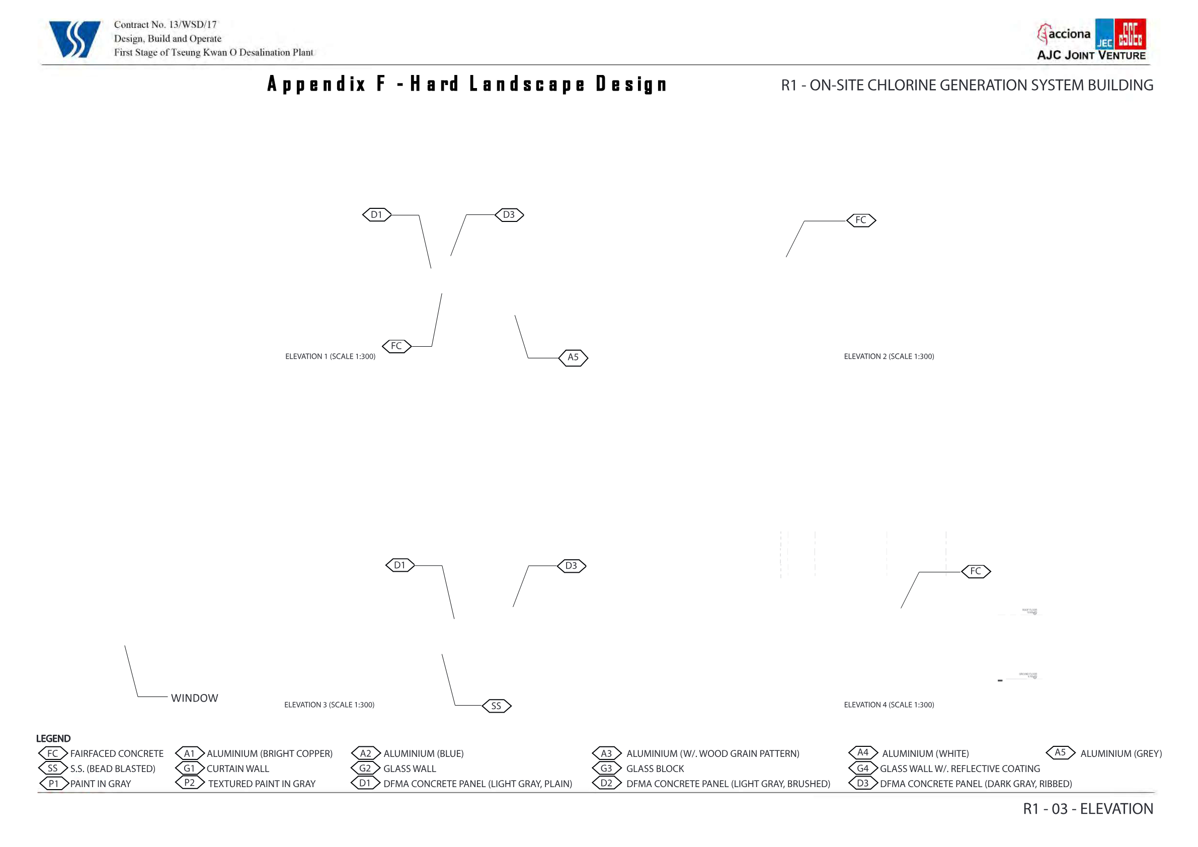
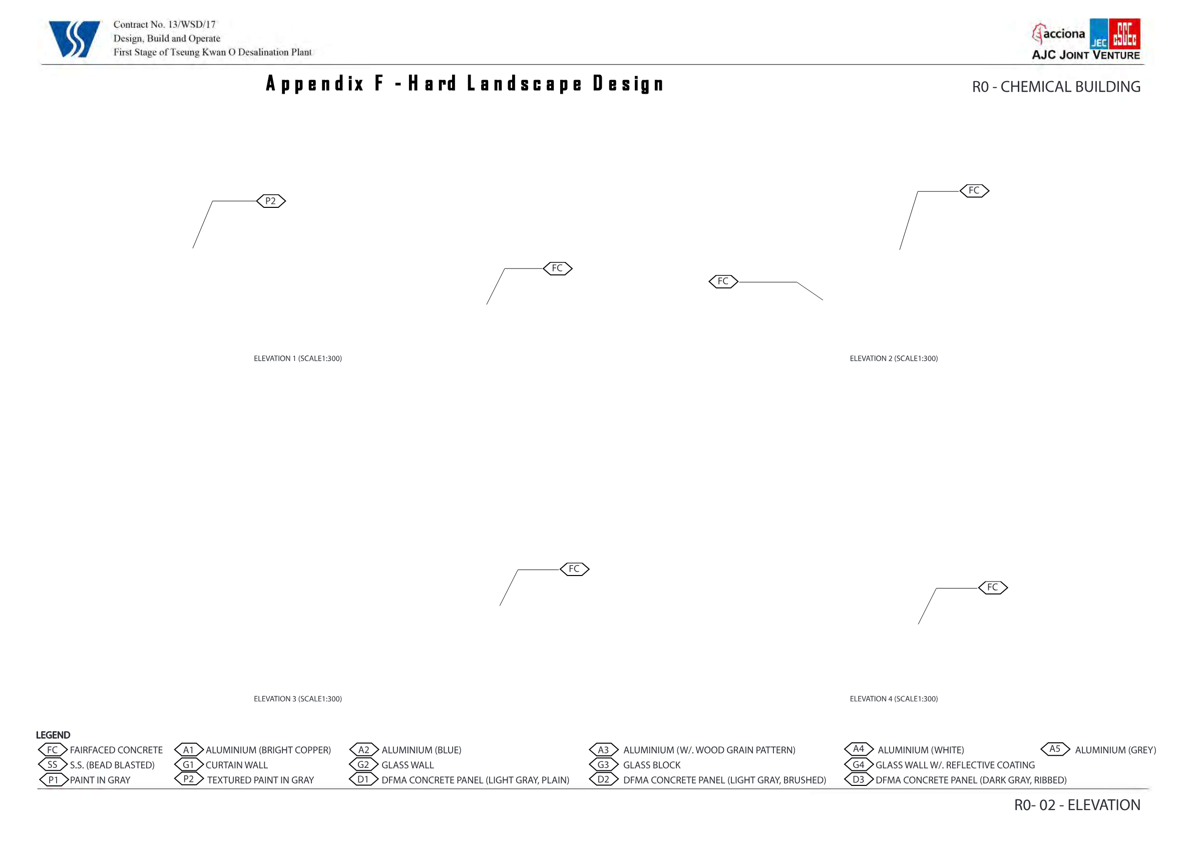
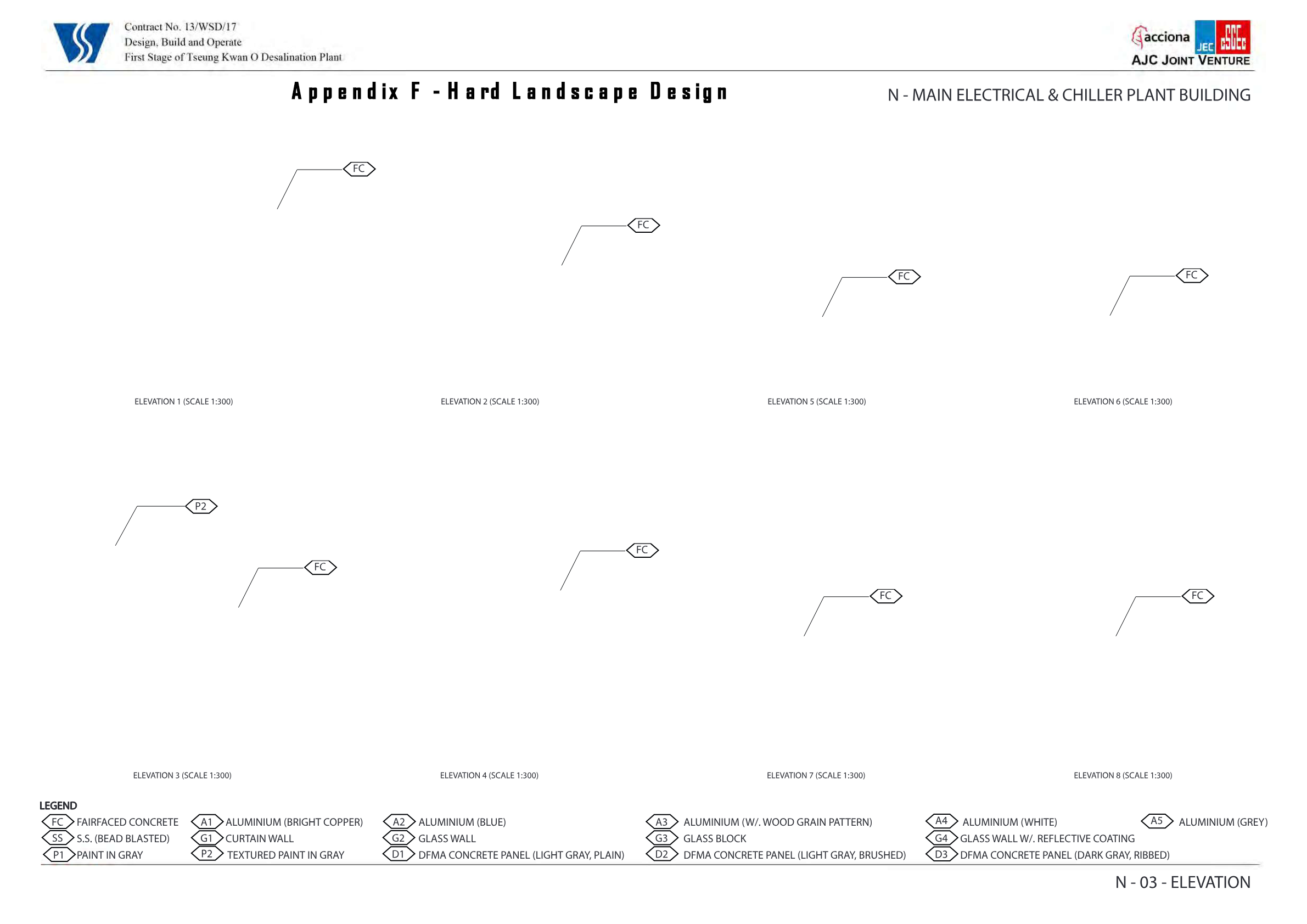
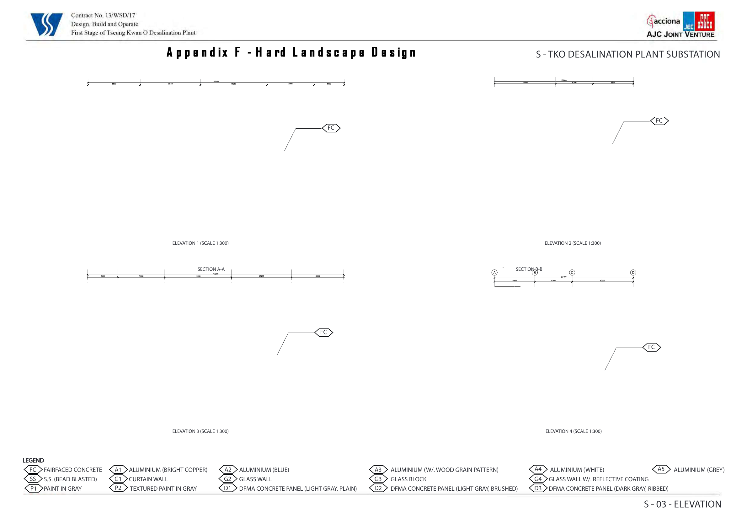
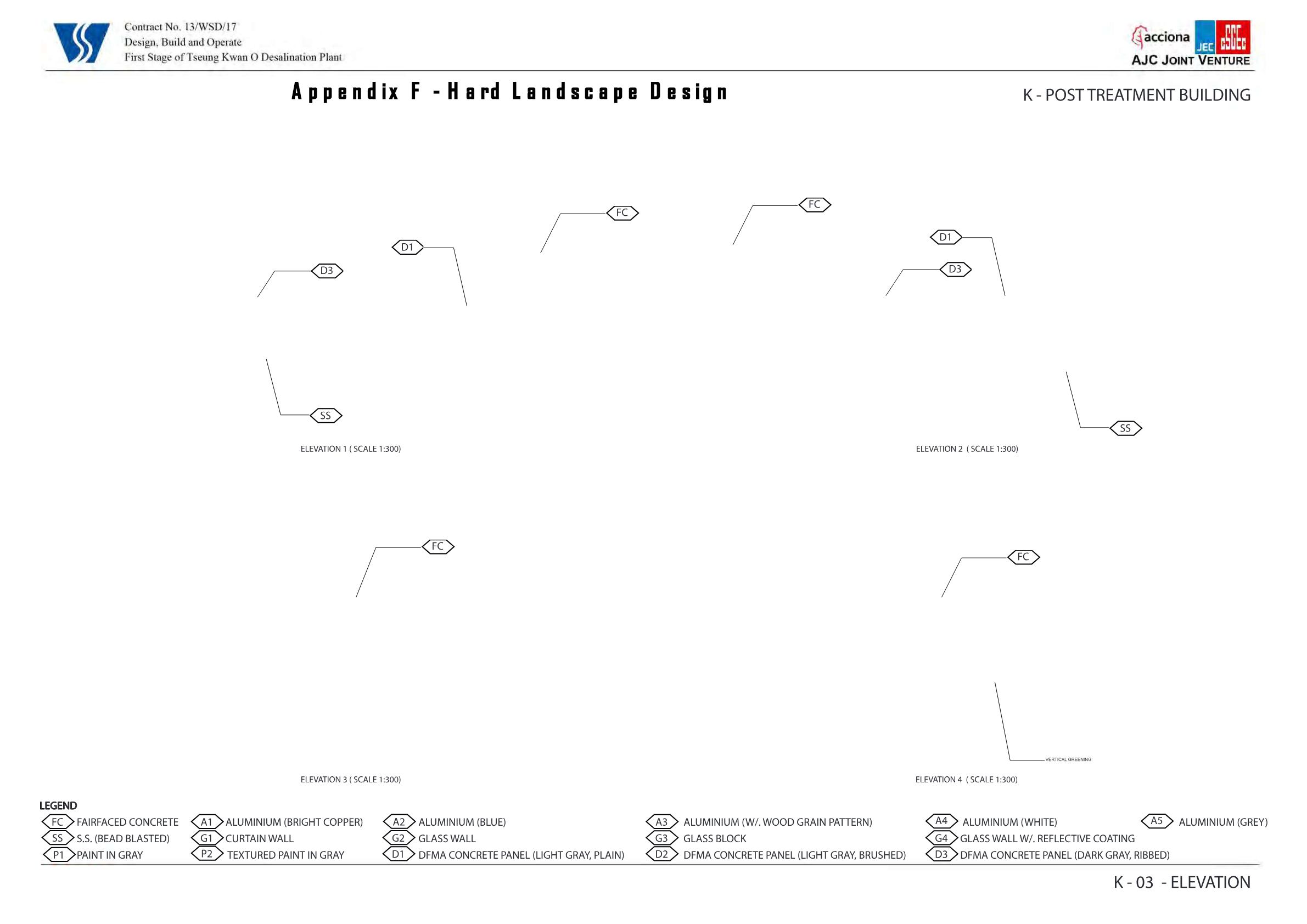
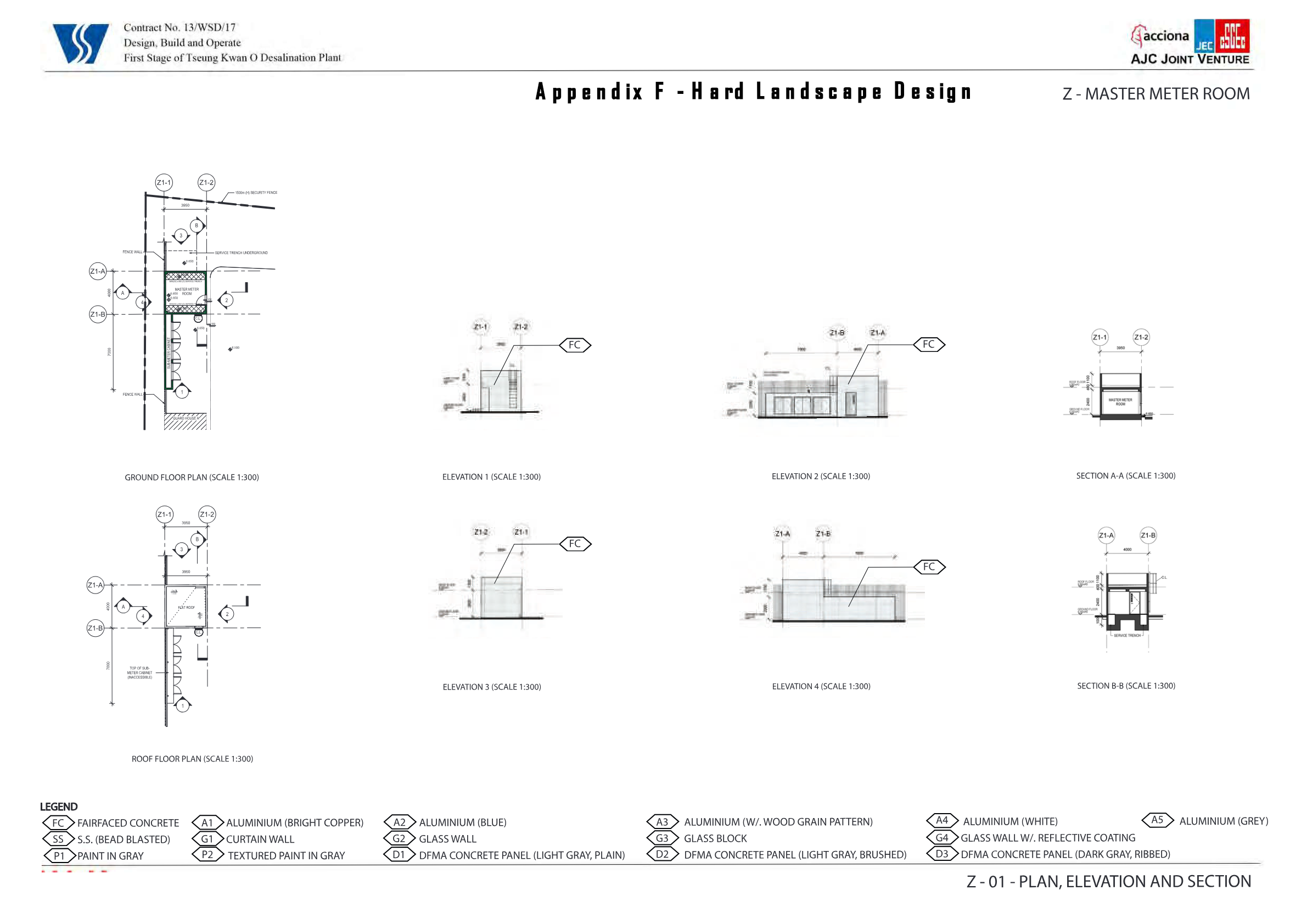
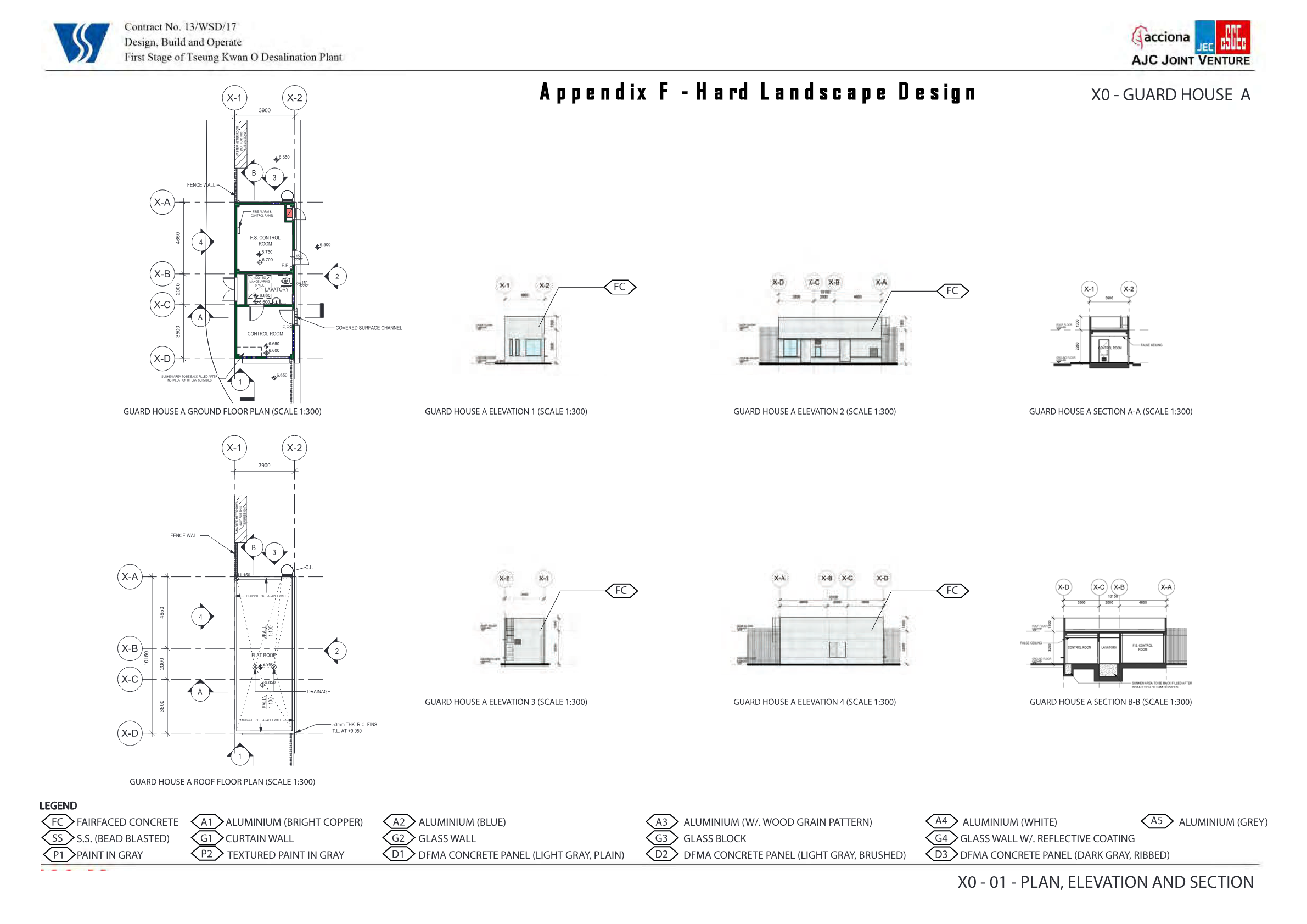
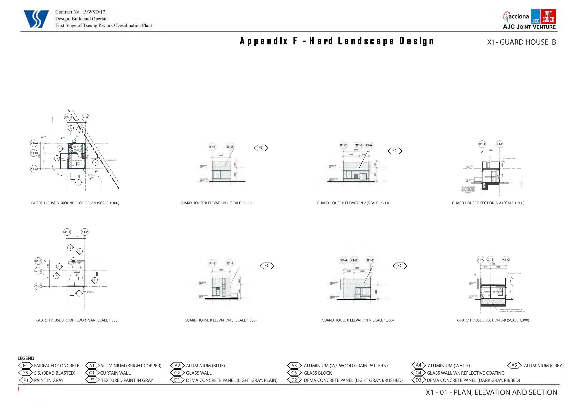
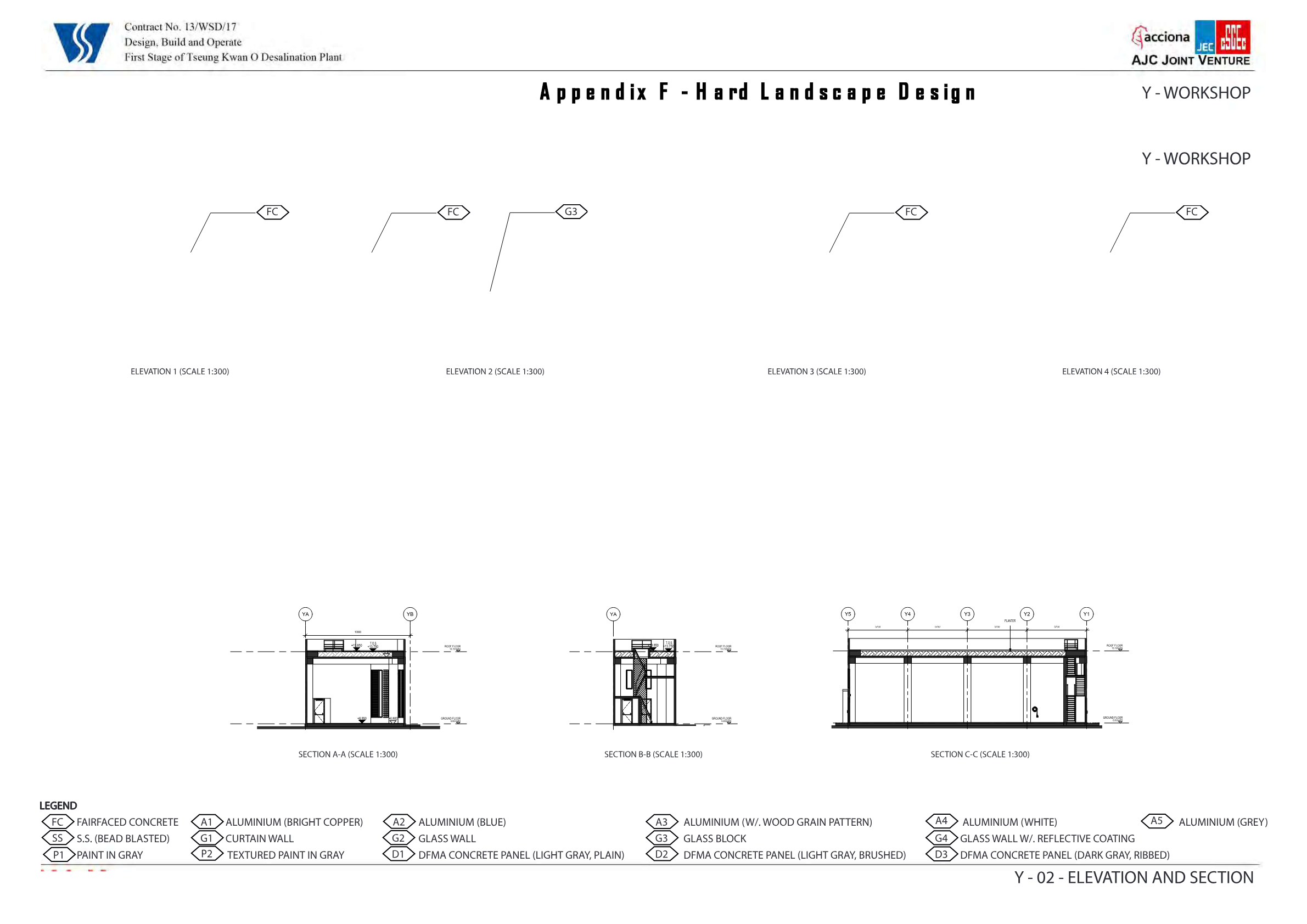

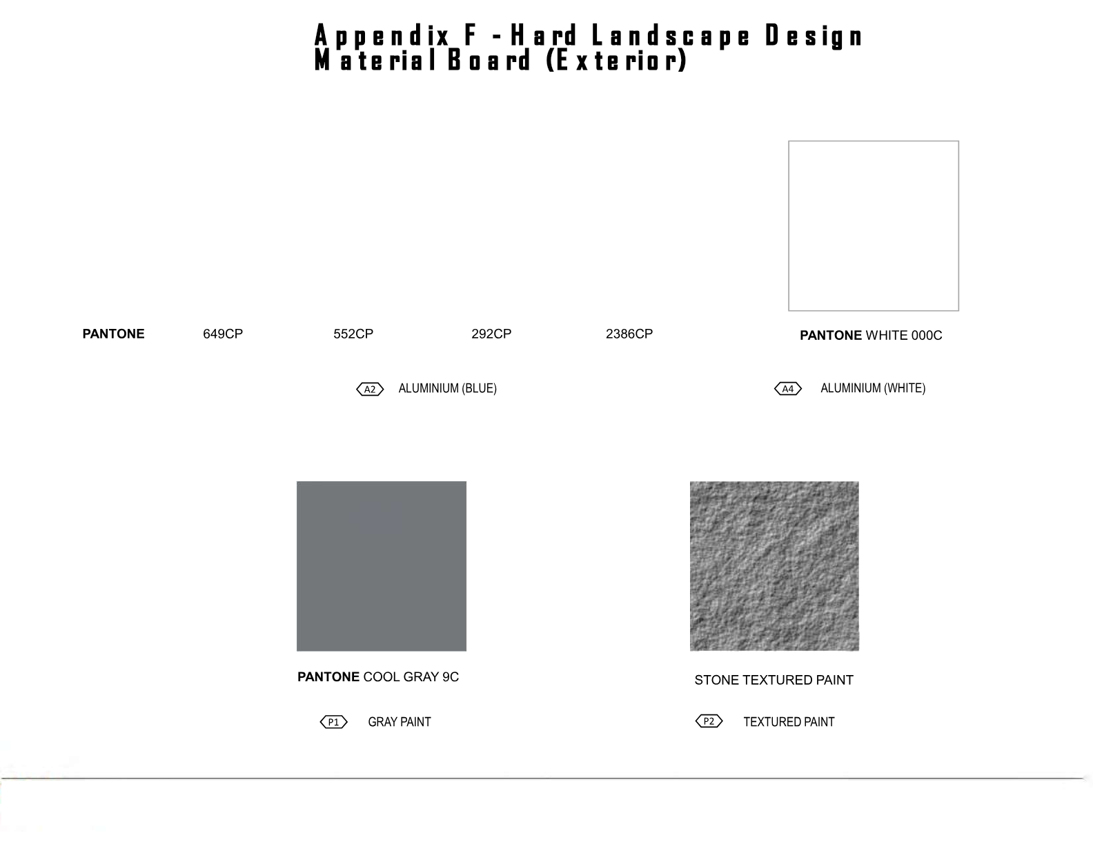
Appendix F - Hard Landscape Design
Landscape Design | Pavement
1 ( "Uunmnnansnnn
I
I
CR
1‘
mVll
110
7‘lunn"lLszanumazmziussuzunaunnaum
[I
u
mes
r
A
7 II It
l
"Hi
L
Hl
5 ♦
' t
—
! It
3 |
I o
I
t"
: T
950 h hff]
—- - aal l < -
! -
ihr
r L
iEFr
d
J.
■ 11 u
I
151 4 ip
rdd
k
6 5
1—5
| !||
|
i
BE
1 AIHFAFALip.
IF
I
1 Concrete Road
t ■
Paver Block
1——
Wash Granolith Paving
0 5 10
20 50m
PAVING MODULE PLAN
MATERIAL SCHEDULE
(ILLUSTRATION OF DIFFERENT COLOURS OF THE RANDOM MIX OF PAVING BLOCKS) ■ .
3 “ t
ao
Y
100x200x60mm THK.
COLOUR: BROWN
PERCENTAGE: 50%
(
2‘
" ?
«C
.1
1,
1
Th
KK.
2
%
$
1.
1
am
L
-3
—V
Per
pade
-- a
EE
rP
_____
100x200x60mm THK.
COLOUR: LIGHT BROWN
PERCENTAGE: 30%
"t
1 00 •
t
4 N
----- -
I
r
Amma
—r
L
<■
V
100x200x60mm THK.
COLOUR: GREY
PERCENTAGE: 20%
eh
C.
f
d
. se%
8&
}
A_ _
1‘
)i/ • (
ri
in
00000 ■
PAVER BLOCK
WASH GRANOLITH PAVING
=Fi
(.
1 <
..
: 3. n
—a
8
-
d- .
CONCRETE ROAD
(FOR VEHICULAR)
Dam
—
Appendix A - Figure A12
TKO Desalination Plant
Appendix F - Hard Landscape Design (Paving Pattern)
Landscape Design | Typical Details
s
(A
MI
0 5 10m
17m
5m
8m
<
>
>
>
<
<
J
——m
a
w
. n
. ‘I,
“ i
—Th.
a.
t
oeeHe
4m
*
w
—
■
200X100X60mm THK. (PEDESTRIAN)
CONCRETE PAVER BLOCKS
Typical Kerb Detail
Paving Pattern
(ILLUSTRATION OF DIFFERENT COLOURS OF THE RANDOM MIX OF PAVING B
125
rn
100 27
FFL
250X125X250mm (H)
PRE-CAST CONCRETE K1 KERB
MIN. 20mm COMPACTED AND 7-10mm
LEVELLING SAND COURSE
' 11
kes
I .
ON EDGE SET LEVEL AND
POINTED IN 1:3 C/S MORTAR
100x200x60mm THK.
COLOUR: BROWN
PERCENTAGE: 50%
I
IE
*
2209080/05.3
O
O
4 2 OCC
FFL
4 R.C STRUCTURE BY ENGINEER
, e
TivunTy
I
l -
O
100x200x60mm THK.
COLOUR: LIGHT BROW
PERCENTAGE: 30%
100mm COMPACTED
GRANULAR SUB-BASE
d
A
100x200x60mm THK.
COLOUR: GREY
PERCENTAGE: 20%
100mm COMPACTED
GRANULAR SUB-BASE
.8
1
2
300
r
o8hs
d—।—DC
—
g
4
I
w
l
dI
GRADE 20/20 CONCRETE HAUNCHING
I I
D
i
=mes
Mlll
COMPACTED NORMAL SUB-GRADE
IHIIHI—H
fr• •
--
ILILLTTLLLLLTT
1 ERE
I,
B
l — I — I — I —II—I — I — I — I — I — I — I —
Appendix A - Figure A11
TKO Desalination Plant